
Modern hydride vapor-phase epitaxy system & methods

a technology of hydride vapor phase and epitaxy, which is applied in the direction of crystal growth process, polycrystalline material growth, chemically reactive gas growth process, etc., can solve the problems of parasitic growth chamber wall deposits, inability to use gacl/sub>3/sub>3 for hvpe, and unattractive industrial applications, etc., to achieve uniform flow rate

Active Publication Date: 2011-06-30
CBL TECH
View PDF7 Cites 37 Cited by
  • Summary
  • Abstract
  • Description
  • Claims
  • Application Information

AI Technical Summary

Benefits of technology

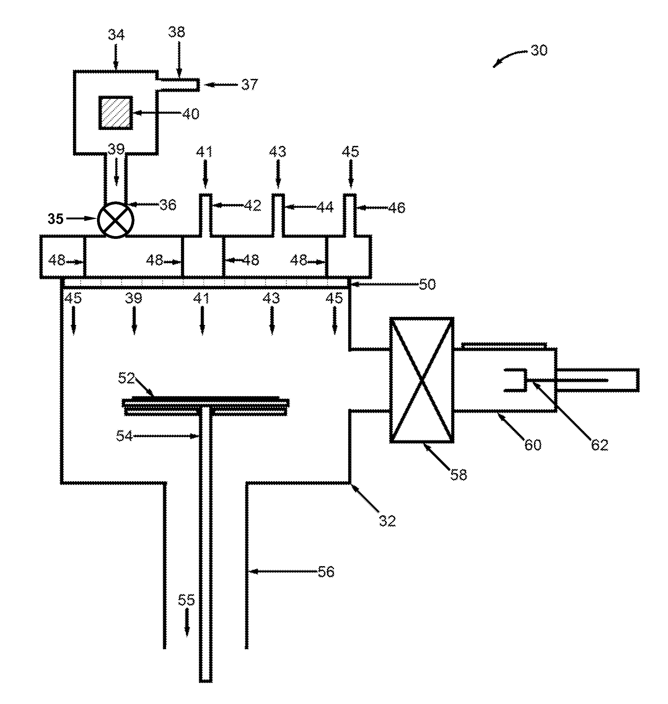
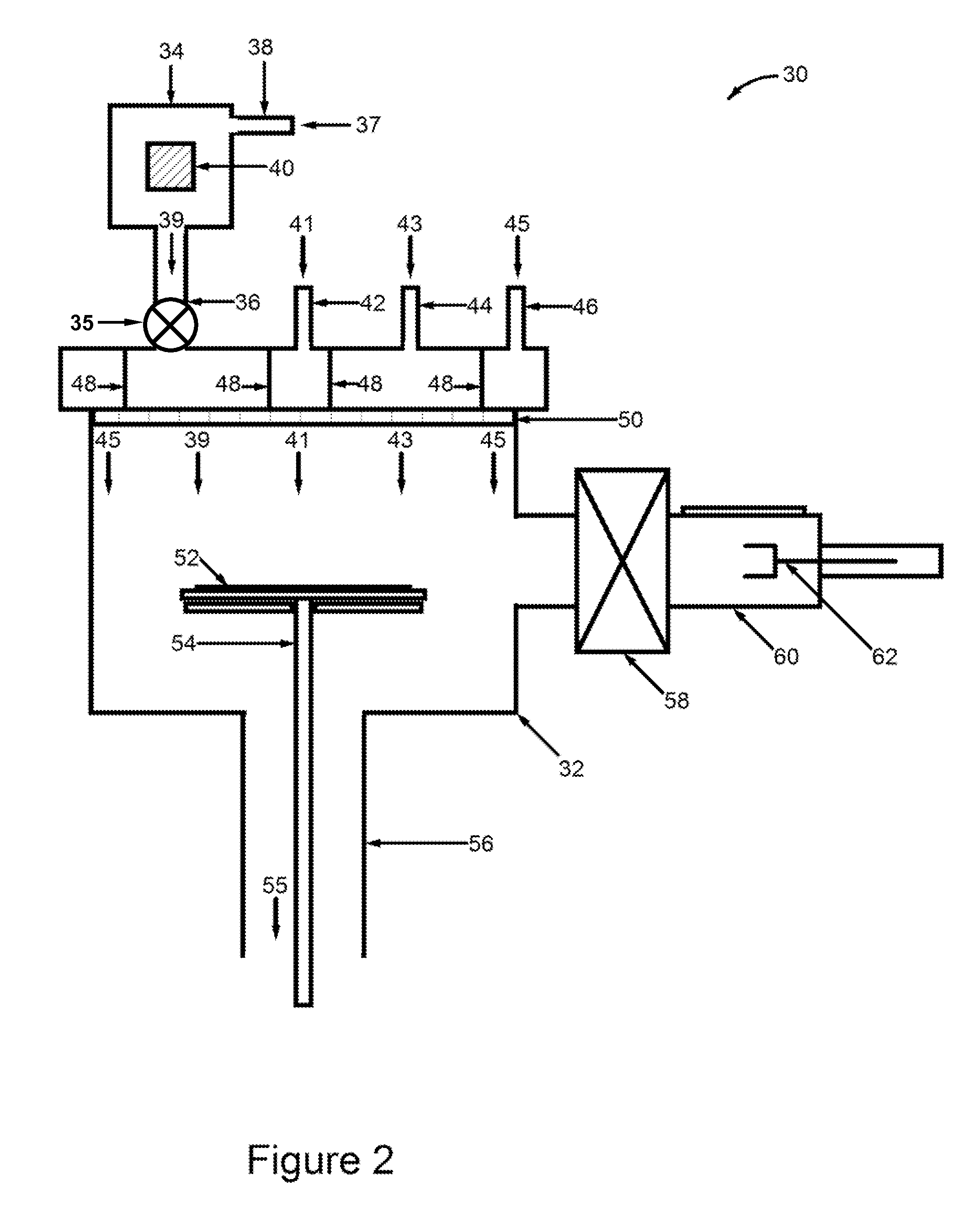
The present invention provides a new type of HVPE deposition system for the efficient growth of gallium nitride, gallium arsenide, and other compounds. The system has several components that allow for improved growth and reduced wall deposition. These components include an external reactant source chamber, a growth chamber with an internal substrate heater, a gas isolation / diffuser plate, and low pressure operation. The new design also allows for the separation of reactant gas species and the use of multiple reactant source chambers. These technical effects improve the quality and yield of the HVPE process.

Problems solved by technology

While HVPE allows for high growth rates of GaN, there are certain difficulties associated with HVPE as a technique that have made it unattractive for industrial applications.
GaCl3 cannot be used for HVPE because the presence of the two extra chlorine atoms pushes the growth reaction towards etching rather than deposition.
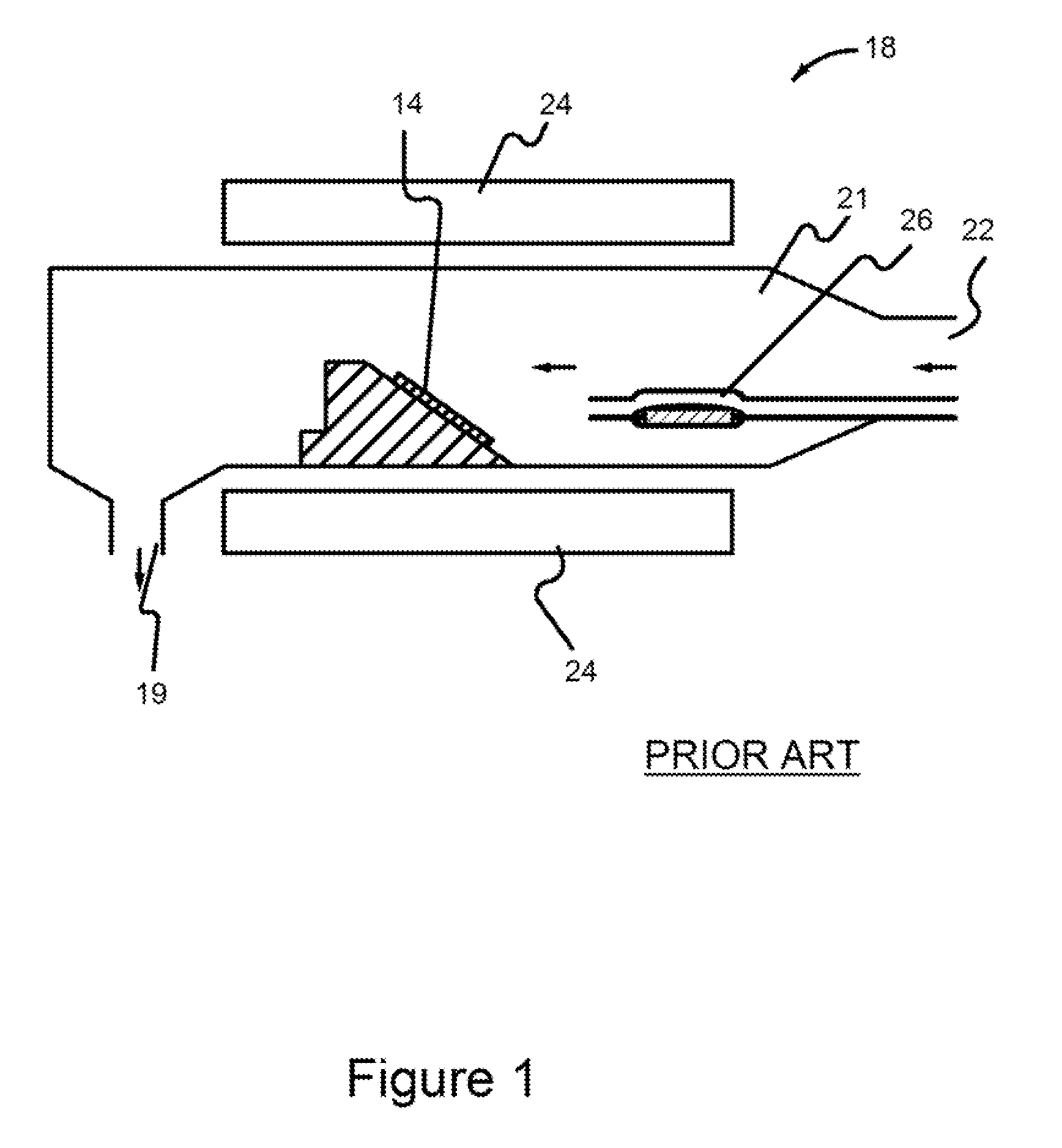
As a result of this, it is necessary to disturb the entire enclosure to service (refill) the metallic source as it becomes depleted with use.
A second limitation to the industrial use of HVPE is the parasitic growth chamber wall deposits.
A third limitation is the mixing of group III and group V reactant compounds such as GaCl and ammonia before the preferred deposition region at the substrate.

Method used


Image

  • Modern hydride vapor-phase epitaxy system & methods
  • Modern hydride vapor-phase epitaxy system & methods
  • Modern hydride vapor-phase epitaxy system & methods

Examples


Embodiment Construction

[0031]Although the following detailed description contains many specific details for the purposes of illustration, anyone of ordinary skill in the art will appreciate that many variations and alterations to the following details are within the scope of the invention. Accordingly, the exemplary embodiments of the invention described below are set forth without any loss of generality to, and without imposing limitations upon, the claimed invention.

[0032]A modern design hydride vapor-phase eptiaxy (HVPE) deposition system capable of producing deposition on a commercial scale is described below. The design addresses and remedies problems with the HVPE technique that have limited its commercial implementation. The design of this HVPE deposition system is especially applicable to growth of III-V materials such as Ga(In,Al)As, Ga(In,Al)N, Ga(In,Al)P, and Ga(In,Al)Sb. The system design includes several aspects. A first aspect is a metal source that is external to the reactor and that incorp...


PUM

PropertyMeasurementUnit
operating pressureaaaaaaaaaa
temperatureaaaaaaaaaa

Abstract

Hydride vapor-phase deposition (HVPE) systems are disclosed. An HVPE hydride vapor-phase deposition system may include a reactant source chamber and a growth chamber containing a susceptor coupled to the reactant source chamber. The reactant source chamber may be configured to create a reactant gas through a chemical reaction between a solid or liquid precursor and a different precursor gas. The reactant source chamber can be configured to operate at a temperature T(M) significantly above room temperature. The reactant gas can be chemically unstable at or near room temperature. The susceptor is configured to receive a substrate and maintain the substrate at a substrate temperature T(S). The growth chamber includes walls can be configured to operate at a temperature T(C) such that T(M), T(S) are greater than T(C).

Description

FIELD OF THE INVENTION[0001]Embodiments of the present invention relate to hydride vapor phase epitaxy and more specifically to a new hydride-vapor phase epitaxy deposition system that overcomes limitations to repeated high-quality deposition of thick epitaxial layers.BACKGROUND OF THE INVENTION[0002]Hydride vapor-phase epitaxy (HVPE) is an important technique for the epitaxial growth of various semiconductors, such as gallium nitride, an important technological material. For example, GaN is currently used in the manufacture of blue light emitting diodes, semiconductor lasers, and other opto-electronic devices. The background of the related art will be discussed with particular reference to the deposition of GaN, although all of the discussion can be applied to several other compounds such as GaAs.[0003]HVPE is a currently favored technique for GaN buffer layer deposition, because it provides relatively rapid growth in a cost-effective manner. It is also favored in producing thick s...

Claims


Application Information

Patent Timeline
Patent Type & Authority Applications(United States)
IPC IPC(8): C30B25/10C30B25/08C30B25/14
CPCC30B25/08C30B29/406C30B25/10
Inventor SOLOMON, GLENN S.MILLER, DAVID J.
Owner CBL TECH
Learn More