
Liquid Submerged, Horizontal Computer Server Rack and Systems and Method of Cooling such a Server Rack

Active Publication Date: 2011-06-09
GREEN REVOLUTION COOLING
View PDF48 Cites 161 Cited by
  • Summary
  • Abstract
  • Description
  • Claims
  • Application Information

AI Technical Summary

Benefits of technology

[0025]Briefly, the present invention provides novel apparatus, systems, and methods for efficiently cooling computing devices having heat-generating electronic components, such as, for example, independently operable servers immersed in a dielectric liquid coolant in a tank.
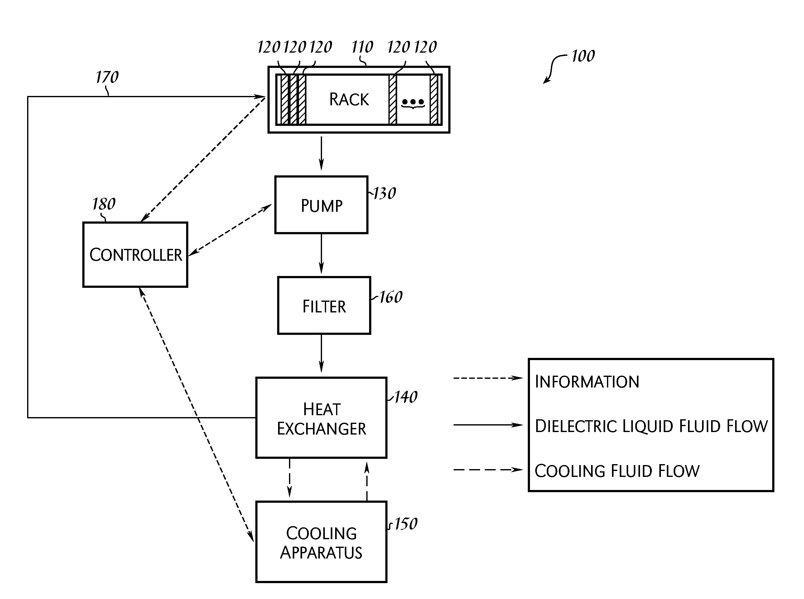
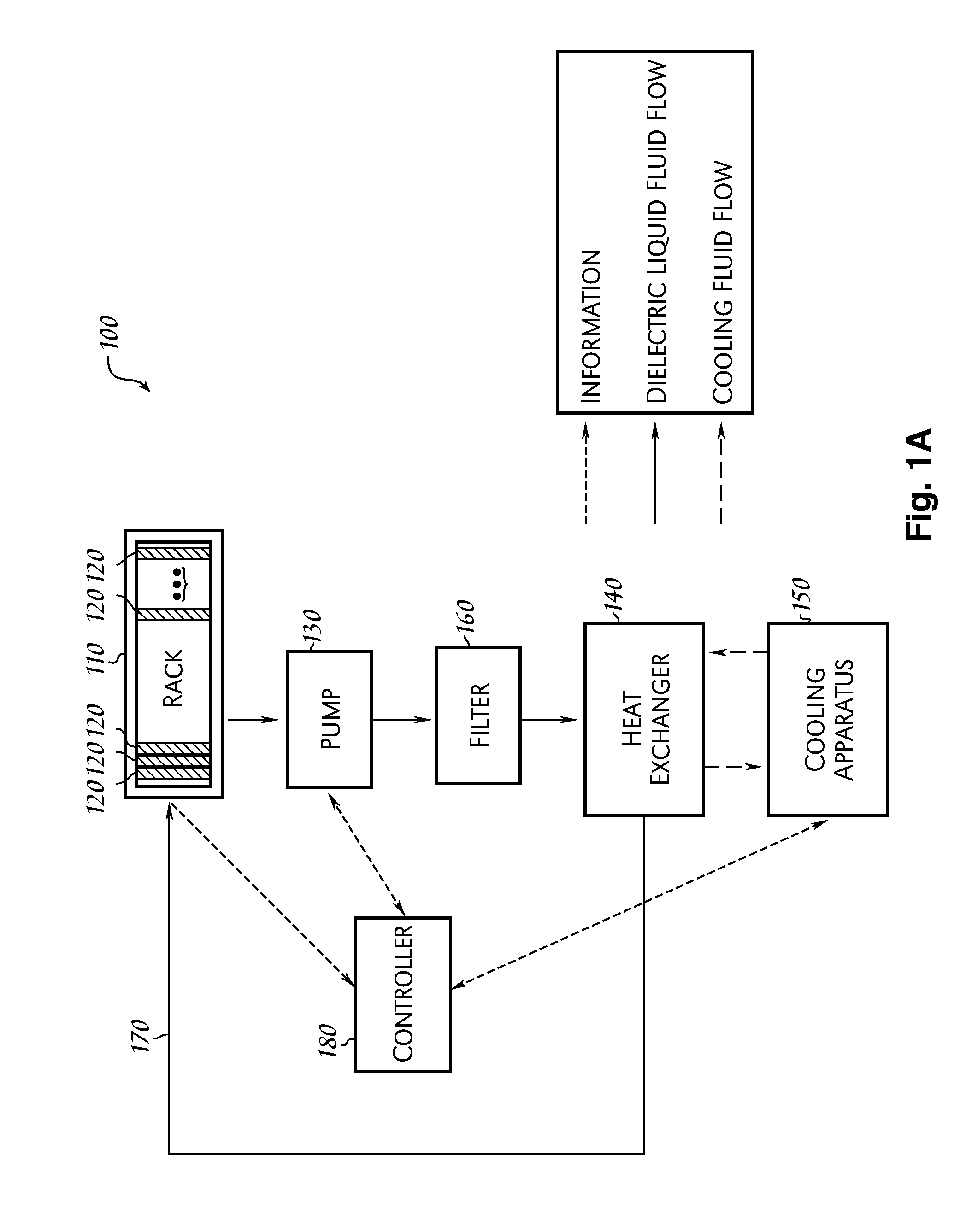
[0026]The system may include at least one tank defining an interior volume and having a coolant inlet for receiving a dielectric liquid coolant within the interior volume and having a coolant outlet for allowing the dielectric liquid coolant to flow from the interior volume, the coolant inlet and the coolant outlet being fluidly coupled to each other; one or more mounting members positioned within the interior volume and configured to mountably receive a plurality of independently operable servers; a dielectric liquid coolant; a heat exchanger fluidly coupled to the coolant outlet of the at least one tank, the heat exchanger being distally located from the tank; a pump fluidly coupled to the heat exchanger and the interior volume of the at least one tank, the pump being configured for pumping the liquid coolant through a fluid circuit comprising a first circuit portion extending from the coolant inlet of the tank to each server, a second circuit portion extending from each respective server to the coolant outlet, a third circuit portion extending from the coolant outlet to the heat exchanger, and a fourth portion extending from the heat exchanger to the coolant inlet; a controller for monitoring the temperature of the dielectric liquid coolant at at least one location within the fluid circuit and for adjusting the flow of the dielectric liquid coolant through the fluid circuit in order that the dielectric liquid coolant is maintained at an elevated temperature as it exits the second circuit portion of the fluid circuit; wherein the at least one tank is configured for containing the dielectric liquid coolant within the interior volume such that, when the plurality of servers are mountably received therein, each server is submerged within the dielectric liquid coolant for sufficiently cooling each respective server while maintaining the exiting heated liquid coolant at the elevated temperature to reduce the amount of energy consumed to sufficiently cool each of the plurality of servers.
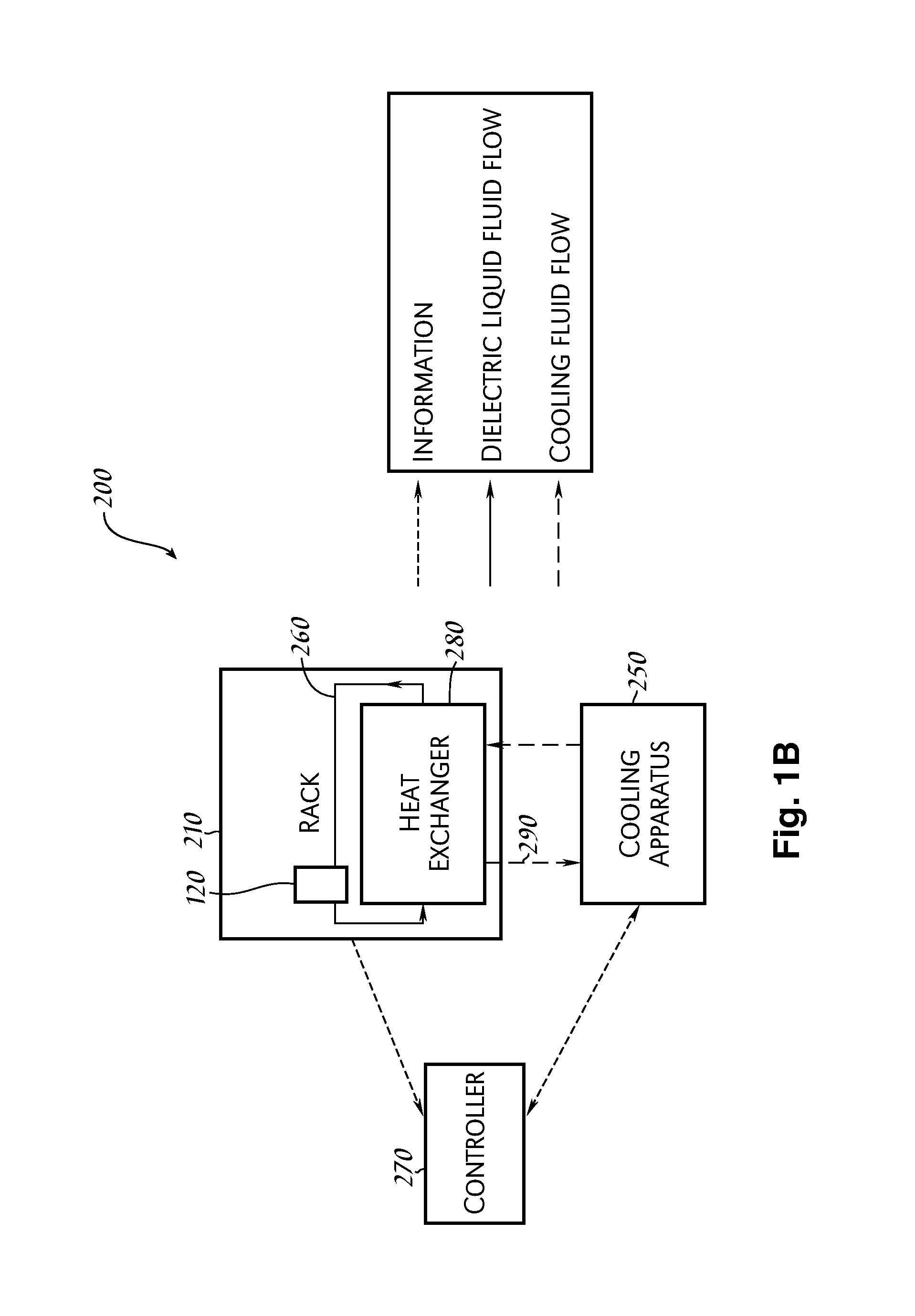
[0027]Alternatively, the cooling system includes at least one tank defining an open interior volume; one or more mounting members positioned within the open interior volume and configured to mountably receive a plurality of independently operable servers within the interior volume; a dielectric liquid coolant circulating in a first fluid circuit through the plurality of servers; a secondary cooling system having a cooling fluid flowing in a second fluid circuit wherein the secondary cooling system rejects heat from the cooling fluid; a coupler located within the at least one tank for thermally coupling heated dielectric coolant from the portion of the first fluid circuit exiting the plurality of servers within the tank to the cooling fluid in the second fluid circuit for rejecting heat from such heated dielectric coolant; a controller for monitoring the temperature of the dielectric liquid coolant at at least one location within the first fluid circuit and for adjusting the flow of the cooling fluid through the second fluid circuit in order that the heated dielectric liquid coolant exiting the plurality of servers is maintained approximately at an elevated temperature wherein the elevated temperature is a temperature significantly higher than the typical comfortable room temperature for humans and lower than the maximum permissible temperature of the most sensitive heat generating electronic component in the plurality of servers; wherein the at least one tank is configured for containing the dielectric liquid coolant within the interior volume such that, when the plurality of servers are mountably received therein, at least a substantial portion of each server is submerged within the dielectric liquid coolant for sufficiently cooling each respective server when the tank is sufficiently full of the liquid coolant maintaining the liquid coolant [exiting] the plurality of servers at approximately the elevated temperature to reduce the amount of energy consumed to sufficiently cool each respective server.
[0028]Alternatively, the cooling system may include at least one tank defining an open interior volume; one or more mounting members positioned within the open interior volume and configured to mountably receive a plurality of independently operable servers within the interior volume; a dielectric liquid coolant circulating in a first fluid circuit through the plurality of servers; a secondary cooling system having a cooling fluid flowing in a second fluid circuit wherein the secondary cooling system rejects some of the heat from the cooling fluid; a coupler located within the at least one tank for thermally coupling heated dielectric coolant from the portion of the first fluid circuit exiting the plurality of servers within the tank to the cooling fluid in the second fluid circuit for rejecting some of the heat from such heated dielectric coolant; a controller for monitoring the temperature of the dielectric liquid coolant at at least one location within the first fluid circuit and for adjusting the flow of the cooling fluid through the second fluid circuit in order that the heated dielectric liquid coolant exiting the plurality of servers is maintained approximately at an elevated temperature wherein the elevated temperature is a temperature significantly higher than the typical comfortable room temperature for humans and lower than the maximum permissible temperature of the most sensitive heat generating electronic component in the plurality of servers; wherein the at least one tank is configured for containing the dielectric liquid coolant within the interior volume such that, when the plurality of servers are mountably received therein, each server is submerged within the dielectric liquid coolant for sufficiently cooling each respective server and maintaining the liquid coolant exiting the plurality of servers at approximately the elevated temperature to reduce the amount of energy consumed to sufficiently cool each respective server.
[0029]The fixture or server rack apparatus includes at least one tank defining an open interior volume and having a coolant inlet for receiving a dielectric liquid coolant within the open interior volume and having a coolant outlet for allowing the coolant to flow from the open interior volume, the coolant inlet and the coolant outlet being fluidly coupled to each other; and one or more mounting members positioned within the interior volume and configured to mountably receive a plurality of servers in a vertical orientation within the interior volume for minimizing the footprint of the server relative to the ground and with the front of the server facing upward for easy installation and removal of each of the plurality of servers without removing or disturbing any other server; wherein the at least one tank is configured for containing a dielectric liquid coolant within the interior volume such that, when a plurality of servers are mountably received therein, each server being mountably received is submerged within the dielectric liquid coolant for sufficiently cooling each respective server when the tank is sufficiently full of the liquid coolant.

Problems solved by technology

Electricity, personnel, and construction costs continue to increase and server hardware costs are decreasing, making the overall cost of cooling a large and growing part of the total cost of operating a data center.
In general, electronic components of higher performing servers dissipate correspondingly more power.
Consequently, as energy costs and power dissipation continue to increase, the total cost of cooling a data center has also increased.
Such a low cooling capacity can significantly add to the cost of building a data center, since data centers can cost as much as about $250 per-square-foot to construct.
As the air-cooling example implies, commercially available methods of cooling have not kept pace with increasing server and data-center performance needs, or the corresponding growth in heat density.
As a consequence, adding new servers to existing data centers has become difficult and complex given the effort expended to facilitate additional power dissipation, such as by increasing an existing data center's air conditioning capacity.
Various alternative approaches for cooling data centers and their servers, e.g., using liquid cooling systems, have met with limited success.
For example, attempts to displace heat from a microprocessor (or other heat-generating semiconductor-fabricated electronic device component, collectively referred to herein as a “chip”) for remotely cooling the chip have been expensive and cumbersome.
Accordingly, these liquid-cooling systems have been designed for particular component layouts and have been unable to achieve large-enough economies of scale to become commercially viable.
However the costs to capitalize such cooling were not mentioned, and indicators suggest that saving electricity requires expensive equipment.
Immersion cooling of electronic components has been attempted in high-performance (e.g., computer gaming) applications, but has not enjoyed widespread commercial success.
Such systems have been expensive, and offered by a limited number of suppliers.
Refrigeration as a primary mode of cooling, directly or indirectly, requires significant amounts of energy.
Two-phase cooling systems have been attempted, but due to technical complexity, they have not resulted in cost-effective products or sufficiently low operating costs to justify investing in two-phase-cooling capital.
Accordingly, each method of server or computer cooling currently employed or previously attempted have been prohibitively expensive and / or insufficient to meet increasing cooling demands of computing devices.
Although chips capable of delivering desirable performance levels while operating at a lower relative power have been offered by chip manufacturers, such chips have, to date, been expensive.
Consequently, cooling approaches to date have resulted in one or more of a high level of electricity consumption, a large capital investment and an increase in hardware expense.

Method used


Image

  • Liquid Submerged, Horizontal Computer Server Rack and Systems and Method of Cooling such a Server Rack
  • Liquid Submerged, Horizontal Computer Server Rack and Systems and Method of Cooling such a Server Rack
  • Liquid Submerged, Horizontal Computer Server Rack and Systems and Method of Cooling such a Server Rack

Examples


Embodiment Construction

[0053]The following describes apparatus, systems, and methods for efficiently cooling computing devices having heat-generating electronic components, such as, for example, independently operable servers at least partially immersed in a dielectric liquid coolant in a tank. The principles of the invention(s) embodied therein and their advantages are best understood by referring to FIGS. 1-17.

[0054]As used herein, the term “server” generally refers to a computing device connected to a computing network and running software configured to receive requests (e.g., a request to access or to store a file, a request to provide computing resources, a request to connect to another client) from client computing devices, includes PDAs and cellular phones, also connected to the computing network. Such servers may also include specialized computing devices called blade servers, network routers, data acquisition equipment, movable disc drive arrays, and other devices commonly associated with data ce...


PUM

PropertyMeasurementUnit
Temperatureaaaaaaaaaa
Flow rateaaaaaaaaaa
Volumeaaaaaaaaaa

Abstract

Apparatus, systems, and methods for efficiently cooling computing devices having heat-generating electronic components, such as, for example, independently operable servers, immersed in a dielectric liquid coolant in a tank.

Description

CROSS-REFERENCES TO RELATED APPLICATIONS[0001]This application claims priority pursuant to 35 U.S.C. 119 to the following U.S. provisional patent applications:[0002]Ser. No. 61 / 188,589 entitled LIQUID SUBMERGED, HORIZONTAL COMPUTER SERVER RACK filed Aug. 11, 2008;[0003]Ser. No. 61 / 163,443 entitled LIQUID SUBMERGED, HORIZONTAL COMPUTER SERVER RACK filed Mar. 25, 2009; and[0004]Ser. No. 61 / 165,470 entitled LIQUID SUBMERGED, HORIZONTAL COMPUTER SERVER RACK filed Mar. 31, 2009.FIELD OF INVENTION[0005]This application concerns cooling of heat-generating electronics such as, for example, rack mounted servers in data centers.BACKGROUND[0006]In 2006, data centers in the United States (U.S.) accounted for about 1.5% (about $4.5 billion) of the total electricity consumed in the U.S. This data center electricity consumption is expected to double by 2011. More than one-third of data center electricity consumption is for cooling servers, which could equate to more than about 1% of all U.S. elect...

Claims


Application Information

Patent Timeline
IPC IPC(8): F28D15/00
CPCH05K7/20763H05K7/20381F28D15/00H05K7/20H05K7/20781Y10T29/4973G06F1/20G06F2200/201H05K7/20281H01L2924/0002H05K7/20836H05K7/20327G06F1/206H05K7/203H01L2924/00H05K7/20236H05K7/2079H05K7/20827H05K7/20772
Inventor BEST, CHRISTIAAN SCOTTGARNETT, MARK
Owner GREEN REVOLUTION COOLING
Learn More