
Device for measuring proteins using biosensor

a biosensor and protein technology, applied in the direction of instruments, material electrochemical variables, material impedance, etc., can solve the problems of difficult reproducibility, difficult to achieve consistent quality of sensors, and complex measurement of glycosylated protein concentration, etc., to achieve accurate measurement, shorten measurement time, and reduce the effect of tim

Inactive Publication Date: 2011-05-26
I SENS INC
View PDF5 Cites 6 Cited by
  • Summary
  • Abstract
  • Description
  • Claims
  • Application Information

AI Technical Summary

Benefits of technology

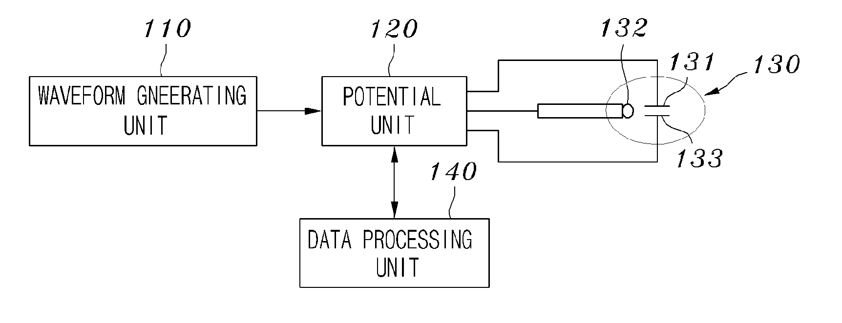
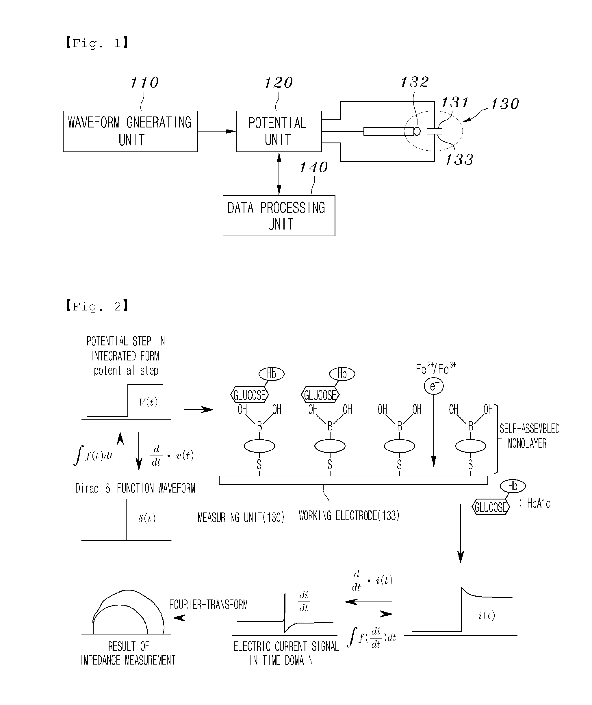
To solve the above problems, the present invention provides a device for measuring protein using biosensor, in which delta function waveform is applied, and impedance of the current signals is computed by Fourier transform to efficiently and accurately measure the concentration of a specific protein in a sample.
With the device according to the present invention, measurement time is shortened and the concentration of proteins may be accurately measured.
The amount of glycated protein may be rapidly and accurately measured improving accuracy and reliability, and the device of the present invention may be available for disposable sensor.

Problems solved by technology

However, it has shortcomings in that expensive antibody is required, and sensors with consistent quality can hardly be achieved due to the inequalities of porous pad.
However, it has difficulties as it requires washing process of boronic acid derivatives, which are lysed with glycosylated protein, and a precise amount of sample should always be maintained to ensure the right results.
However, these conventional electrochemical determining methods of glycosylated protein generally involve collecting glycosylated protein and glycosylated protein-markers competitively on the surface of electrode, and injecting substrate, which stimulates electrochemical reaction with marker, to determine the size of the signal, and is thus has complicated measurement of the concentration of glycosylated protein and can hardly be reproducible.

Method used


Image

  • Device for measuring proteins using biosensor
  • Device for measuring proteins using biosensor
  • Device for measuring proteins using biosensor

Examples


embodiment 1

Measurement of Glycated Protein Based on Impedance Using Fourier Transform

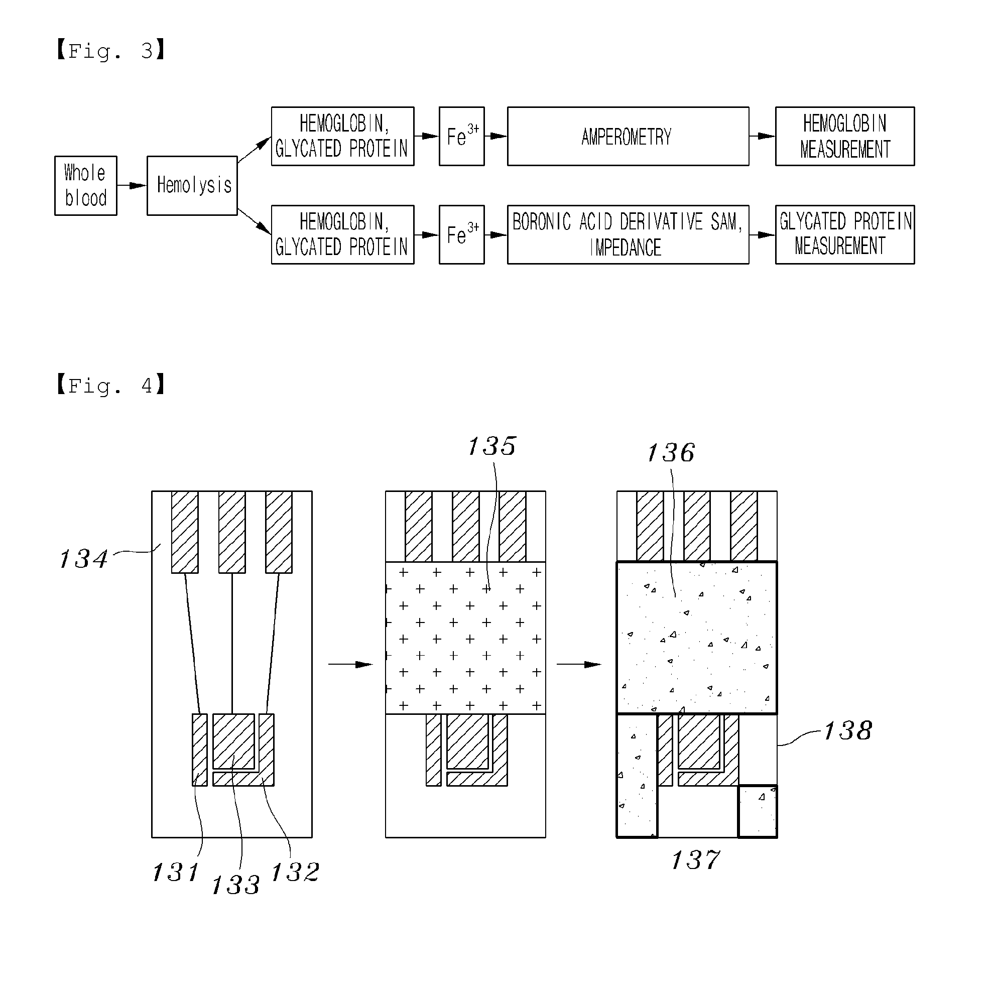
The experiment is based on the method and principle explained above, with the following conditions of the experiment. The buffer solution used blank solution of pH 7.4, 10 mM PBS and 2.5 mM Fe3+, hemolysis blood sample was used, and and glycated hemoblogin was used in a concentration of 4.5%, 5.2%, 7.0%, 9.2% and 11.6%. The SAM was formed on the gold working electrode (133) using 10 mM thiophene boronic acid.

The graphical representation of sensitivity of FIG. 7 indicates the result of measurement in which randomized controlled trial (Rct) was measured according to each concentration and represented in the form of ratio of the blank solution with respect to charge transfer resistance. FIG. 7 represents the measurement of impedance using frequency response analyzer (FRA). The conventional method requires long measurement time and long data processing time to measure the average signal to improve signal-to-noise ...

embodiment 2

applied the same method explained above in Embodiment 1, and the graphical representation of sensitivity and the calibration line of FIGS. 9 and 10 respectively represent the result of measurement.

Referring to FIGS. 9 and 10, the linear increment of impedance in accordance with the increase of concentration of glycated protein confirms the suitability of a device according to the present invention as a biosensor using impedance and also confirms that glycated protein is effectively detected by the impedance method using Fourier transformation.

embodiment 3

Measurement of Glycated Hemoglobin Using Fourier-Transformed Impedance

The method using Fourier-transformed impedance was applied to the electrode of Embodiment 1 by using a potentiostat which has the potential increasing time shorter than 50 ms. Impedance data was collected for the first 2.5 seconds by using 10 mv potential step corresponding to 0.4 Hz. From the data obtained from chronoamperometry, impedance data was computed within a range of 0.4-10 kHz, and cyclic voltammetry was conducted at 400 mV / s scan speed for 2.5 seconds. Stock solution in various concentrations was prepared from 4 mL pH 8.5 buffer solution, and 40 μL was taken from each stock solution and injected into solution containing electrode and oxidation-reduction pair to measure the charge transfer resistance. As for standard substance, JCCLS CRM004a (Japanese Committee for Clinical laboratory Standards) containing 4-13% of glycated hemoglobin with respect to the total amount of hemoglobin (140±10 g / L) was used. ...


PUM


Abstract

A sensor for measuring a protein with a measurement speed improved from a conventional impedance measurement, using a biosensor is provided. The sensor is capable of efficiently and accurately measuring impedance generated by a selective binding to the protein by Fourier-transforming an electric current signal which is obtained by applying a potential signal of a delta function waveform.The device for measuring a protein using a biosensor includes the biosensor including a sample inlet through which a sample is drawn in, a working electrode on which a receptor layer is coated for selective binding to the specific protein in the drawn sample, and a measuring unit including a reference electrode to form a potential difference with the working electrode, a function generator which applies a potential signal in the form of delta function to the working electrode and the reference electrode, and a data processing unit which measures impedance of the working electrode by Fourier-transforming an electric current obtained in response to the delta function waveform.Accordingly, with the device for measuring a protein using a biosensor is capable of measuring concentration of the protein with accuracy, measurement time is shortened and the concentration of protein can be accurately measured by removing the influence of dispersion.

Description

TECHNICAL FIELDThe present invention relates to a device for measuring proteins, and more particularly, to a device for measuring concentration of a specific protein contained in a sample using a biosensor, in which a receptor layer optionally binding to the specific protein is formed on an electrode and impedance generated due to the binding components is measured.BACKGROUND ARTIn recent, there have been increasing demands to measure blood glucose regularly to diagnose and prevent diabetes. Portable measuring instrument, to be specific, the strip-type biosensor is available for users to measure blood glucose easily and conveniently by simply grabbing the instrument in their hands.U.S. Pat. No. 5,541,117 discloses preparing a pad with glycosylated haemoglobin assay-specific antibody fixed thereon, transferring the sample onto the fixed pad, and performing computation based on the intensity of reflected light. However, it has shortcomings in that expensive antibody is required, and s...

Claims


Application Information

Patent Timeline
IPC IPC(8): B01J19/00
CPCG01N33/5438G01N27/3276G01N27/02G01N27/26G01N33/53G01N33/68G01N35/00
Inventor NAM, HAKHYUNPARK, SU-MOONPARK, JIN-YOUNGCHO, JOO YOUNG
Owner I SENS INC
Learn More