
Variable capacity type rotary compressor

Inactive Publication Date: 2011-05-26
LG ELECTRONICS INC
View PDF16 Cites 4 Cited by
  • Summary
  • Abstract
  • Description
  • Claims
  • Application Information

AI Technical Summary

Benefits of technology

[0025]The variable capacity type rotary compressor according to the present invention can facilitate controlling of capacity variation and simplify a piping structure. Also, upon applying such compressor to an air conditioner, a mode switching is facilitated so as to improve comfortableness and energy saving and reduce interference with other pipes, which allows improvement of the assembly of the air conditioner and reduction of the number of valves, thereby decreasing the fabricating cost. Also, a modularized valve is fixed to a casing or accumulator, so as to prevent beforehand the increase in compressor vibration due to the valve and standardize the piping assembly, thereby improving productivity.

Problems solved by technology

However, for employing the inverter motor, a driver for driving the inerter motor is about 10 times as expensive as a driver of a constant-speed motor, thereby rising a fabrication cost of the compressor.
On the other hand, for bypassing the refrigerant, a piping system becomes complicated and accordingly a flow resistance of the refrigerant is increased, thereby lowering efficiency of the compressor.
However, for the independent suction type rotary compressor, since the suction pipes should independently be connected to both cylinders, the number of assembly processes is drastically increased, thereby rising the fabricating cost of the compressor.
Further, in case of a plurality of suction pipes being connected, they are positioned near other members, and thereby a welding space therefor is not ensured.
Accordingly, an automatic assembly process is not available to be performed, thereby further increasing the fabricating cost.
In addition, a mode switching device for varying the capacity of the compressor is installed outside the casing, accordingly it is vibrated when the compressor is vibrated, thereby aggravating the vibration of the compressor.

Method used


Image

  • Variable capacity type rotary compressor
  • Variable capacity type rotary compressor
  • Variable capacity type rotary compressor

Examples


Embodiment Construction

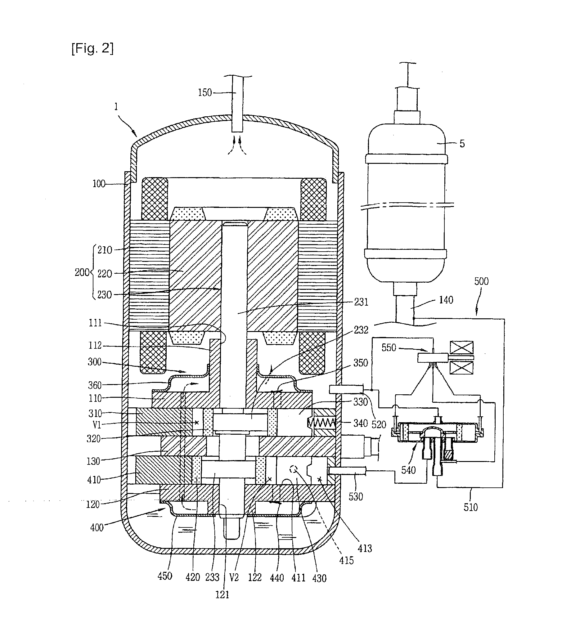
[0040]Description will now be given in detail of a variable capacity type rotary compressor in accordance with one embodiment of the present invention, with reference to the accompanying drawings.

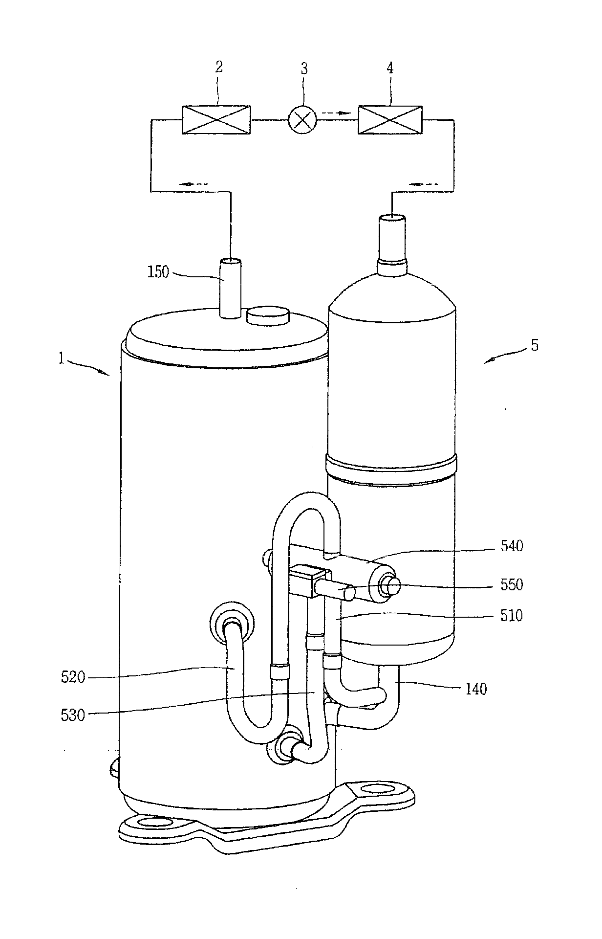
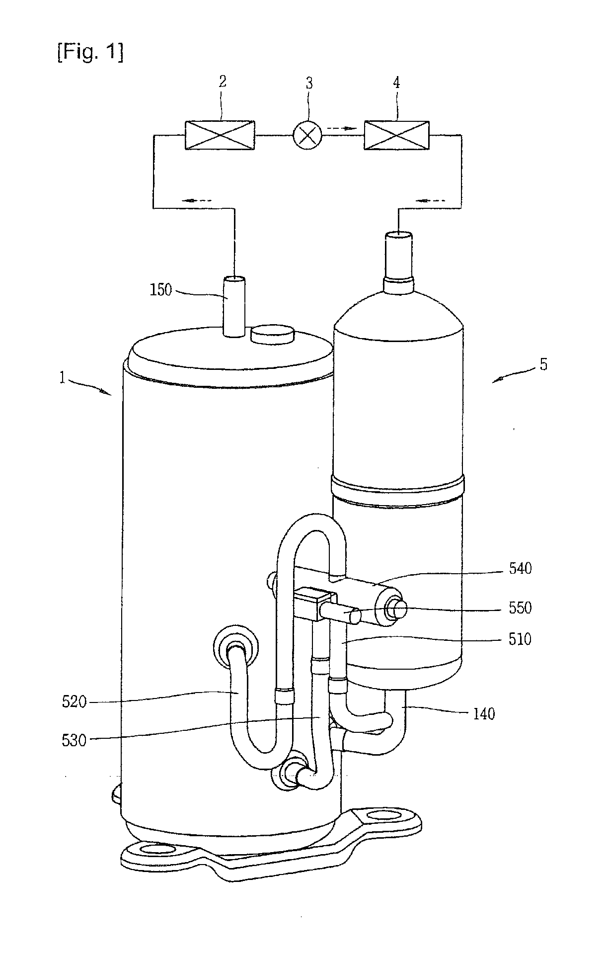
[0041]As shown in FIG. 1, a variable capacity type rotary compressor 1 according to the present invention may be configured such that a suction side thereof is connected to an outlet side of an evaporator 4 and simultaneously a discharge side thereof is connected to an inlet side of a condenser 2 so as to form a part of a closed loop refrigerating cycle including the condenser 2, an expansion apparatus 3 and the evaporator 4. An accumulator 5 for separating a refrigerant carried from the evaporator 4 to the compressor 1 into a gaseous refrigerant and a liquid refrigerant may be connected between the discharge side of the evaporator 4 and the inlet side of the compressor 1.

[0042]The compressor 1, as shown in FIG. 1, may include a motor part 200 installed at an upper side of an inner space of...


PUM


Abstract

Disclosed is a variable capacity type rotary compressor, in which a refrigerant sucked via one suction pipe can be alternately sucked into each compression space via a communication passage between a plurality of cylinders so as to reduce the number of components and the number of assembly processes, thereby remarkably reducing a fabricating cost, a refrigerant within an idling cylinder can be prevented from flowing back into another cylinder so as to improve the performance of the compressor, a welding space can be ensured when connecting connection pipes so as to realize a welding automation, thereby further reducing the fabricating cost, and a mode switching valve can be stably fixed to an appropriate position so as to attenuate noise due to vibration of the compressor.

Description

TECHNICAL FIELD[0001]The present invention relates to a variable capacity type rotary compressor capable of being selectively operated in a saving mode or a power mode.BACKGROUND ART[0002]In general, a refrigerant compressor is applied to a vapor compression type refrigerating cycle (hereinafter, referred to as ‘refrigerating cycle’), such as a refrigerator or an air conditioner. A constant-speed type compressor driven at constant speed and an inverter type compressor capable of controlling rotation speed have been introduced as the refrigerant compressor.[0003]The refrigerant compressors are categorized as follows. A refrigerant compressor, in which a driving motor (typically, an electric motor) and a compression part operated by the driving motor are all installed in an inner space of a hermetic casing, is referred to as a hermetic type compressor, and a compressor of which the driving motor is separately installed outside the casing is referred to as an open type compressor. Home...

Claims


Application Information

Patent Timeline
IPC IPC(8): F04B23/08F04B49/00
CPCF01C21/0863F04C18/3564F04C23/008F04C2270/56F04C2240/804F04C2250/00F04C28/065F04C18/356F04C29/00
Inventor BYUN, SANG-MYUNGKIM, SANG-MO
Owner LG ELECTRONICS INC
Learn More