
Planar communications antenna having an epicyclic structure and isotropic radiation, and associated methods

a technology of epicyclic structure and antenna, applied in the field of plane communications and antennas, can solve the problems of not being able to meet all needs, antennas, sometimes large and impractical for a specific application, and simple euclidian antennas, etc., and achieve the effect of low cos

Active Publication Date: 2011-05-26
HARRIS CORP
View PDF6 Cites 93 Cited by
  • Summary
  • Abstract
  • Description
  • Claims
  • Application Information

AI Technical Summary

Benefits of technology

[0015]In view of the foregoing background, it is therefore an object of the present invention to provide a planar antenna device with stable frequency and sufficient gain that may be worn adjacent a body. It is yet another objective to provide a sufficiently isotropic antenna for unoriented communications devices.
[0022]The antenna device of the present embodiments is scalable to any size and frequency. The antenna may be used in many applications, such as one that needs a low cost flexible planar antenna, e.g. in body wearable patient monitoring devices. The antenna device may be sufficiently isotropic to avoid the need for antenna aiming or orientation when used off the human body.

Problems solved by technology

Unfortunately, antennas have not been reduced in size at a comparative level and often are one of the larger components used in a smaller communications device.
These antennas, however, are sometimes large and impractical for a specific application.
Yet simple Euclidian antennas may not meet all needs, such as operation at small physical size relative wavelength and a self loading antenna structure may be needed.
However, microstrip patch antennas typically are efficient only in a narrow frequency band.
They are poorly shaped for wave expansion, such that microstrip antenna bandwidth is proportional to antenna thickness.
The conductive shield must be of sufficient size and it may reduce efficiency and bandwidth: shield reflections can be akin to the image reversal of a mirror, e.g. 180 degrees out of phase causing signal cancellation.
Instantaneous bandwidth may be unaffected however.

Method used


Image

  • Planar communications antenna having an epicyclic structure and isotropic radiation, and associated methods
  • Planar communications antenna having an epicyclic structure and isotropic radiation, and associated methods
  • Planar communications antenna having an epicyclic structure and isotropic radiation, and associated methods

Examples


Embodiment Construction

[0029]The present invention will now be described more fully hereinafter with reference to the accompanying drawings, in which preferred embodiments of the invention are shown. This invention may, however, be embodied in many different forms and should not be construed as limited to the embodiments set forth herein. Rather, these embodiments are provided so that this disclosure will be thorough and complete, and will fully convey the scope of the invention to those skilled in the art. Like numbers refer to like elements throughout.

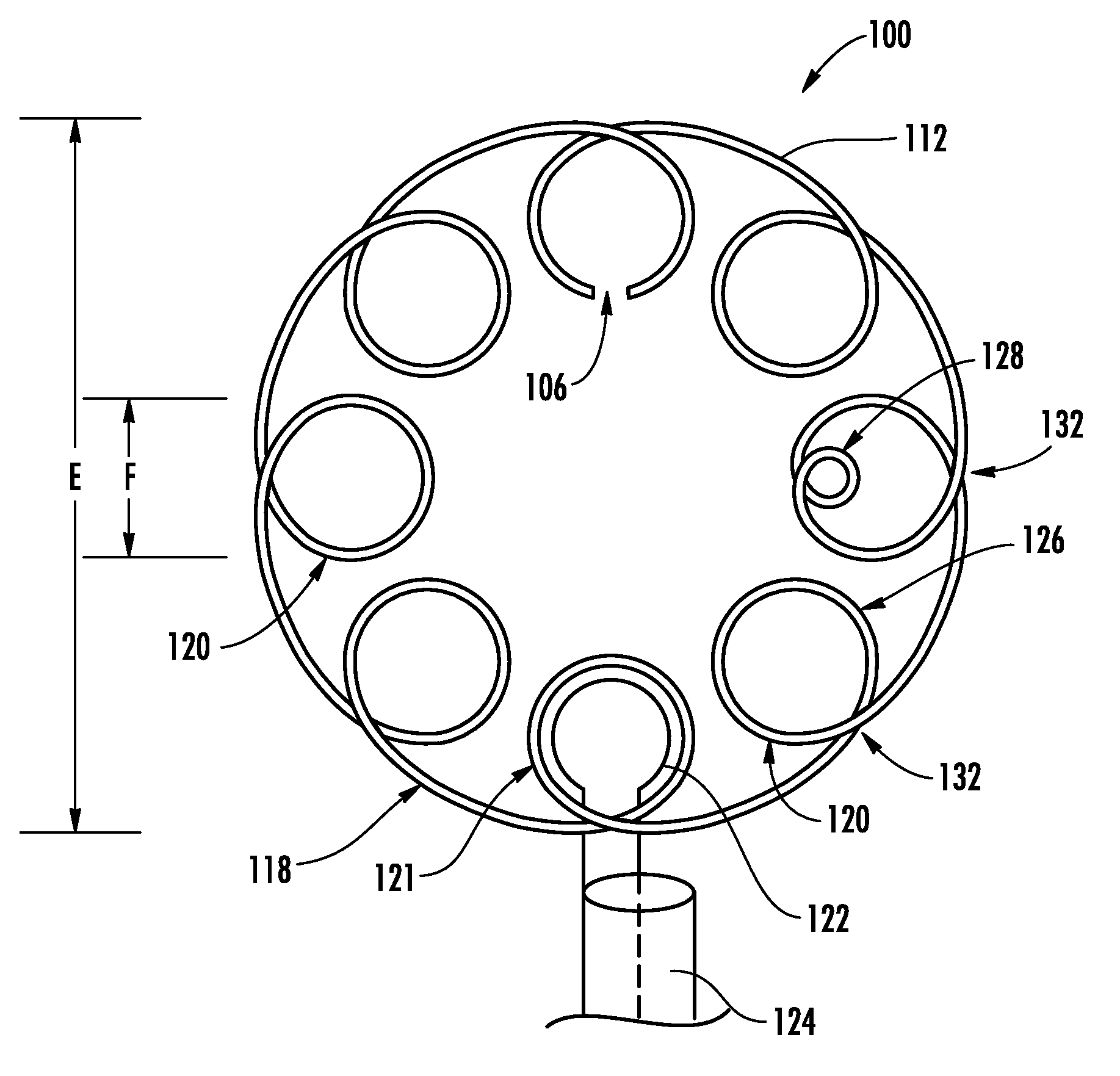
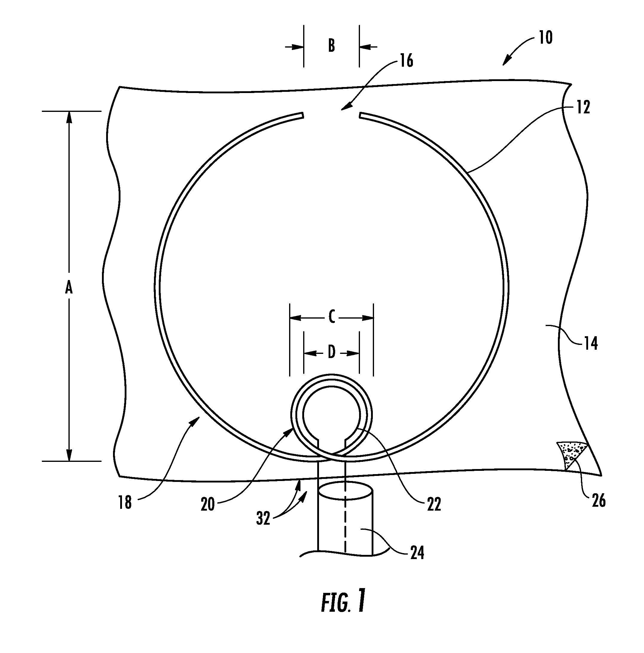
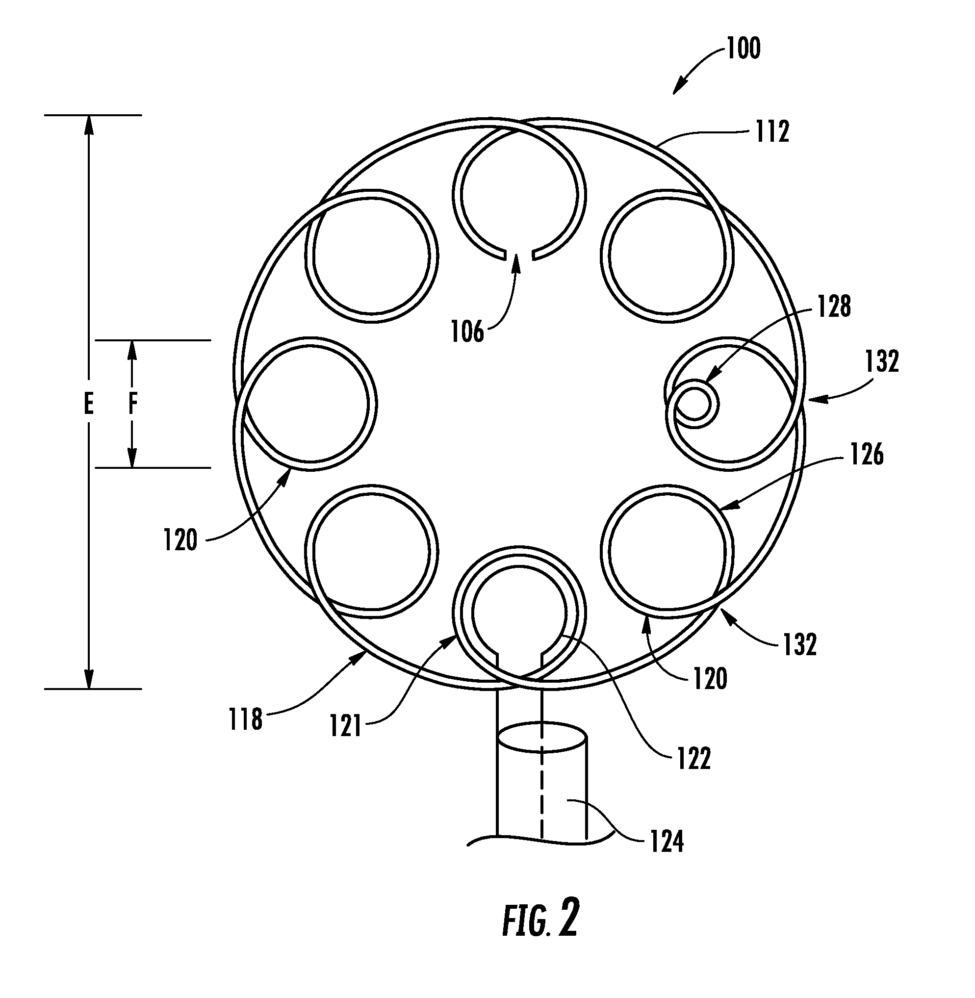
[0030]Referring initially to FIG. 1, a planar antenna device 10 with stable frequency and sufficient gain will be described. Such an antenna device may be used in association with an electronic device or sensor that is worn adjacent a human body, for example. The planar antenna device 10 may be, but is not necessarily, flexible. The antenna device 10 includes an electrical conductor 12 that may reside on a substrate 14 and having at least one gap 16 therei...


PUM

PropertyMeasurementUnit
conductivityaaaaaaaaaa
radiation resistanceaaaaaaaaaa

Abstract

The antenna device includes an electrical conductor extending on a substrate and having at least one gap therein, and with an outer ring portion to define a radiating antenna element, and at least one inner ring portion to define a feed coupler and connected in series with the outer ring portion and extending within the outer ring portion. A coupling feed element is adjacent the at least one inner ring portion, and a feed structure is connected to the coupling feed element to feed the outer ring portion. A plurality of inner ring portions may be provided with the coupling feed element being adjacent a selected one of the plurality of inner ring portions. The plurality of inner ring portions may have a common size and be symmetrically spaced within the outer ring portion. The radiation pattern may be sufficiently isotropic to eliminate the need for antenna aiming. An epicyclic geometry radiating element provides for a compound antenna design.

Description

FIELD OF THE INVENTION[0001]The present invention relates to the field of wireless communications, and, more particularly, to antennas and related methods.BACKGROUND OF THE INVENTION[0002]Newer designs and manufacturing techniques have driven electronic components to small dimensions and miniaturized many communication devices and systems. Unfortunately, antennas have not been reduced in size at a comparative level and often are one of the larger components used in a smaller communications device. It becomes increasingly important in communication applications to reduce not only antenna size, but also to design and manufacture a scalable size antenna having sufficient gain.[0003]In current, everyday communications devices, many different types of patch antennas, loaded whips, copper springs (coils and pancakes) and dipoles are used in a variety of different ways. These antennas, however, are sometimes large and impractical for a specific application. Antennas having diverging electr...

Claims


Application Information

Patent Timeline
Patent Type & Authority Applications(United States)
IPC IPC(8): H01Q1/38H01P11/00H01Q1/00G01R29/00
CPCY10T29/49016H01Q7/00
Inventor PARSCHE, FRANCIS EUGENE
Owner HARRIS CORP
Learn More