
Apparatus and method for generating pulse laser

Inactive Publication Date: 2015-12-24
ELECTRONICS & TELECOMM RES INST
View PDF11 Cites 25 Cited by
  • Summary
  • Abstract
  • Description
  • Claims
  • Application Information

AI Technical Summary

Benefits of technology

The present invention provides an apparatus and method for generating an optical fiber based pulse laser with high power characteristics while stabilizing frequency in a long term basis. Furthermore, this invention allows for quick conversion of the repetition rate of a laser by quickly converting the frequency of an RF oscillator. This results in a stably changing repetition rate of the optical frequency combs.

Problems solved by technology

A laser generated using a solid substance has advantages of low phase noise characteristics while having a wide frequency spectrum, and wavelength conversion characteristics, but also disadvantages of insufficient scalability of its average power, a low efficiency due to difficulty of direct diode laser pumping, large volume, sensitivity to external environments, and difficulty in optical alignment and maintenance and repair due to the complexity of the system.
Since light is sent outside from optical fiber and returned back to the optical fiber, there is much loss of signals, and when alignment is disaligned even slightly, there is much loss of light in the part where light is collected and is entered, which is a big disadvantage.
Furthermore, there is also a problem that the system gets complicated, and stability of the surrounding environment decreases.
Some ideas for resolving these problems were proposed, but since they were all based on using a bulk type pulse stretcher, none could present a fundamental solution.

Method used


Image

  • Apparatus and method for generating pulse laser
  • Apparatus and method for generating pulse laser
  • Apparatus and method for generating pulse laser

Examples


Embodiment Construction

[0030]Hereinafter, embodiments will be described in greater detail with reference to the accompanying drawings. Embodiments are described herein with reference to cross-sectional illustrations that are schematic illustrations of embodiments (and intermediate structures). As such, variations from the shapes of the illustrations as a result, for example, of manufacturing techniques and / or tolerances, are to be expected. Thus, embodiments should not be construed as limited to the particular shapes of regions illustrated herein but may include deviations in shapes that result, for example, from manufacturing. In the drawings, lengths and sizes of layers and regions may be exaggerated for clarity. Like reference numerals in the drawings denote like elements.

[0031]Terms such as ‘first’ and ‘second’ may be used to describe various components, but they should not limit the various components. Those terms are only used for the purpose of differentiating a component from other components. For...


PUM


Abstract

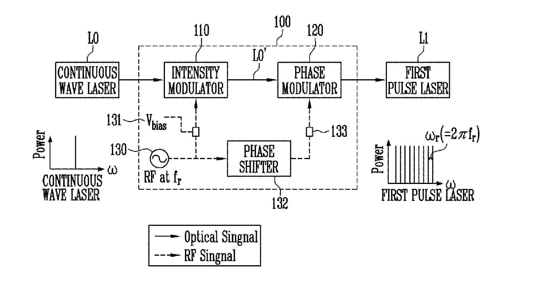
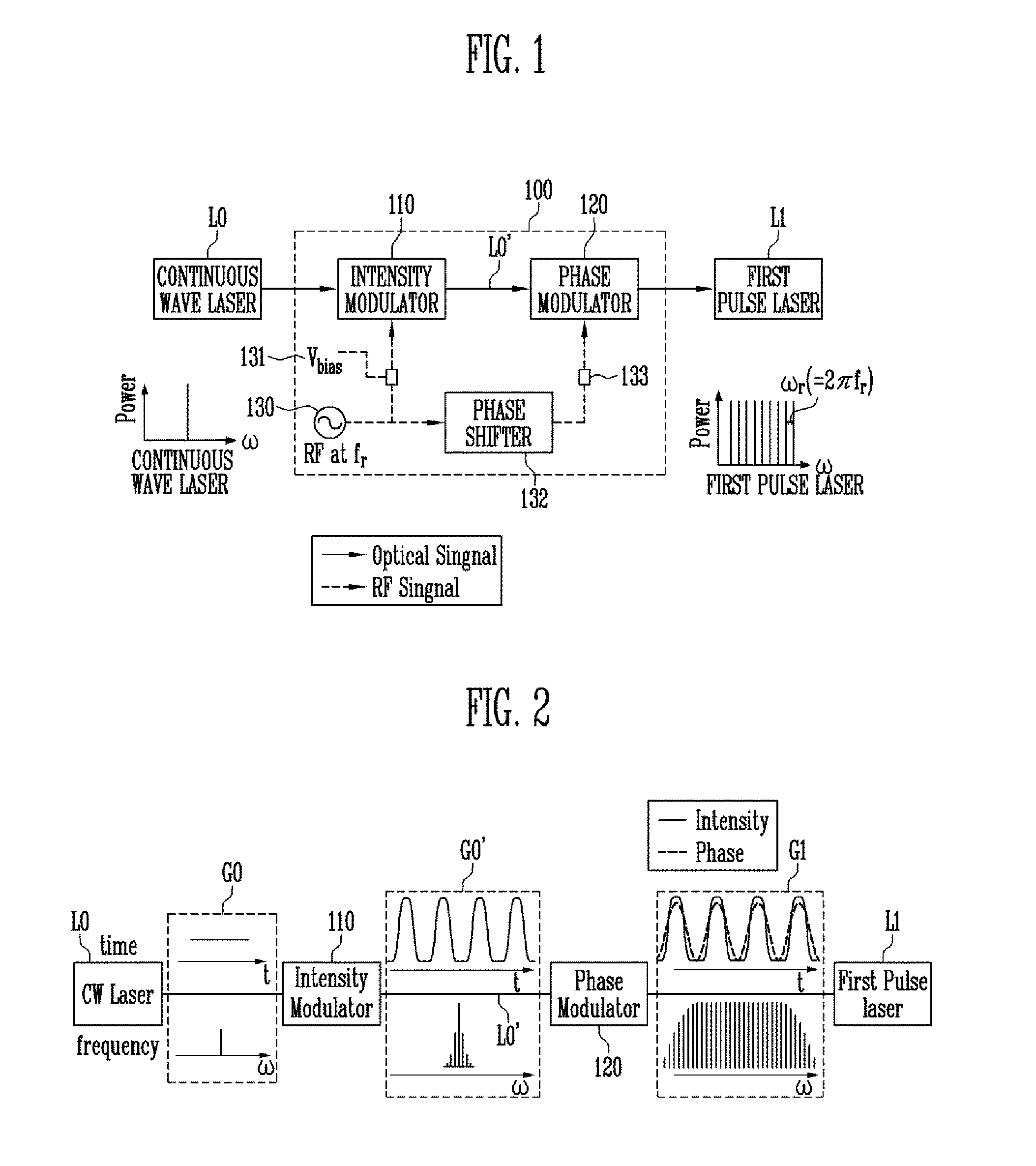
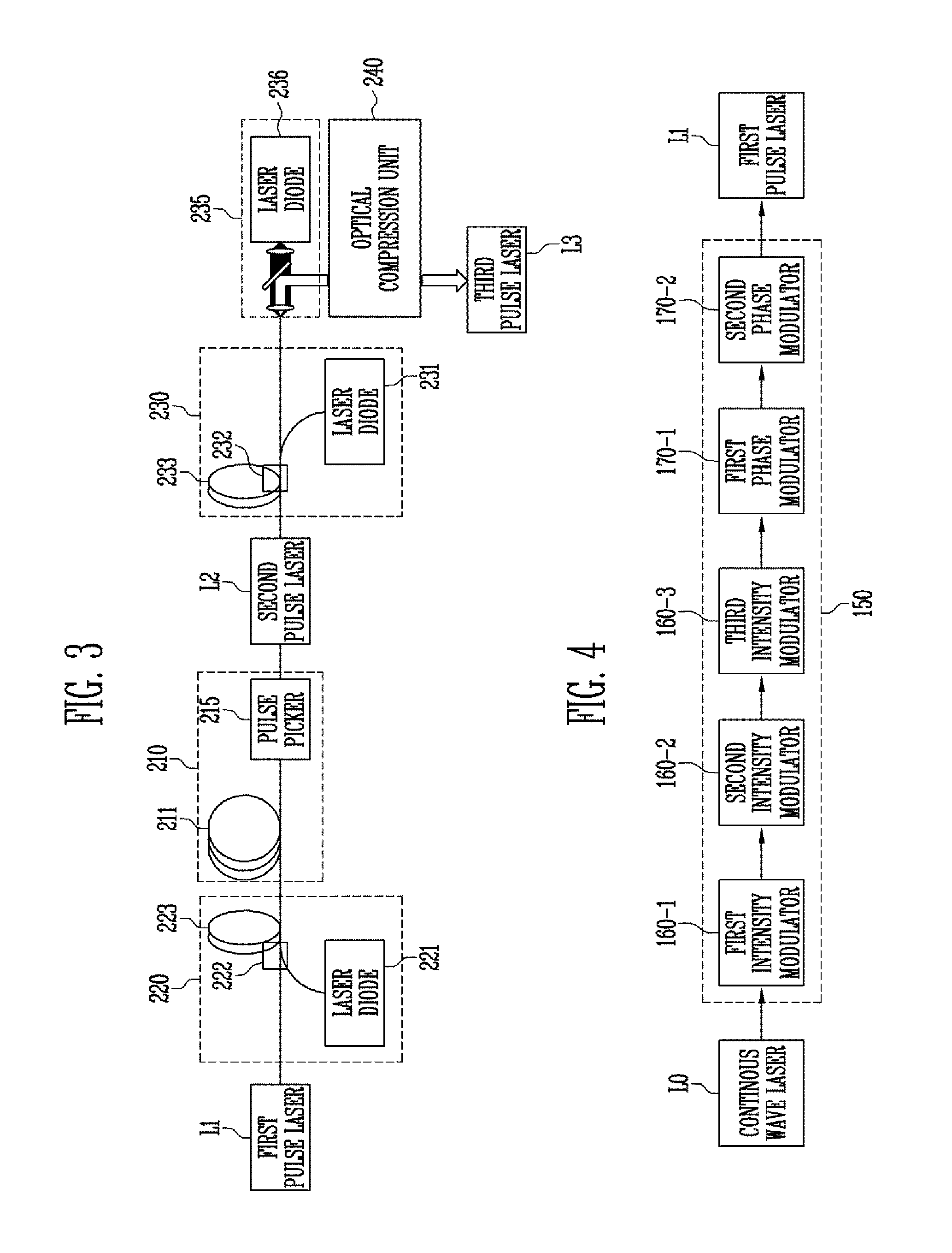
Provided herein is a pulse laser generator including a modulator configured to receive a continuous wave laser, and to modulate an intensity and phase of the continuous wave laser to generate a first pulse laser; and a chirping unit configured to chirp the first pulse laser to generate a second pulse laser.

Description

CROSS-REFERENCE TO RELATED APPLICATION[0001]The present application claims priority to Korean patent application number 10-2014-0074966, filed on Jun. 19, 2014, the entire disclosure of which is incorporated herein in its entirety by reference.BACKGROUND[0002]1. Field of Invention[0003]Various embodiments of the present disclosure relate to an apparatus and method for generating a pulse laser, and more particularly, to an apparatus and method for receiving a continuous wave laser and converting it to a pulse laser that has its basis on optical frequency combs (OFCs) generated by a harmonic wave generation method through phase modulation, and then chirping, amplifying and compressing the pulse laser to generate a pulse having an increased peak power.[0004]2. Description of Related Art[0005]A pulse laser is a laser having a high peak power for a short period of time. It is being used in a wide range of areas including precision spectroscopy, optical frequency measurement, precision di...

Claims


Application Information

Patent Timeline
IPC IPC(8): H01S3/11H01S3/067H01S3/10
CPCH01S3/06754H01S3/0057H01S5/0057H01S5/0265H01S3/0085
Inventor SONG, MIN HYUPMHEEN, BONG KISEO, HONG SEOKKWON, YONG HWANKIM, KI SOOKIM, DONG SUNSONG, JUNG HOSIM, JAE SIKCHOI, GYU DONG
Owner ELECTRONICS & TELECOMM RES INST
Learn More