Controllable-load circuit for use with a load control device
a load control device and control circuit technology, applied in the direction of ac-ac conversion, electric lighting sources, e-light sources, etc., can solve the problem that prior art load circuits may unnecessarily waste power
- Summary
- Abstract
- Description
- Claims
- Application Information
AI Technical Summary
Benefits of technology
Problems solved by technology
Method used
Image
Examples
first embodiment
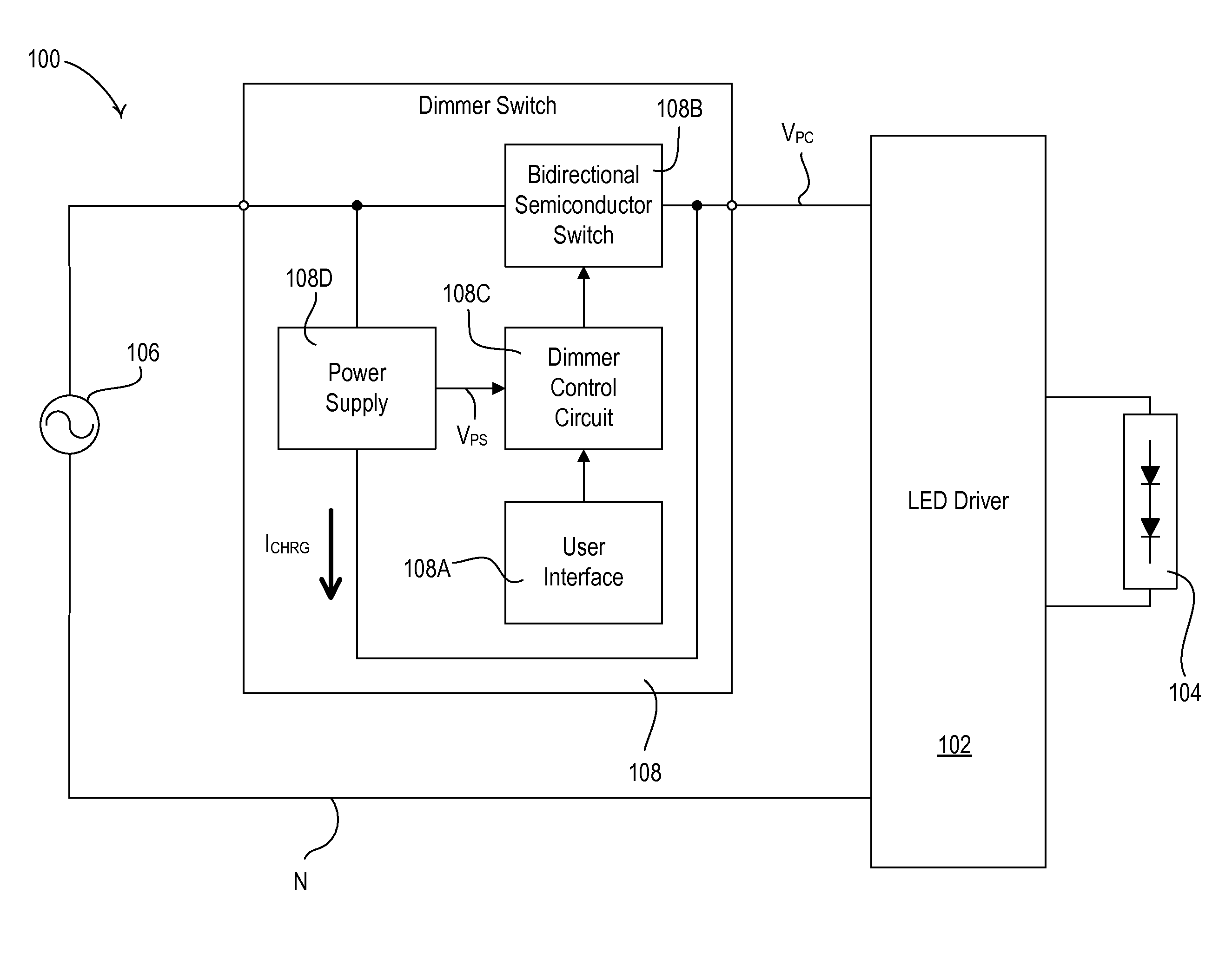
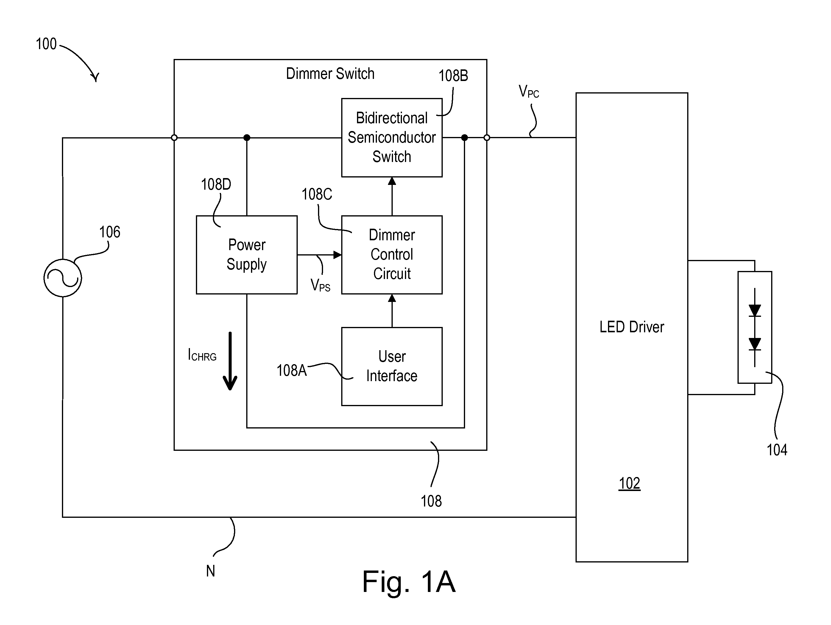
FIG. 1A is a simplified block diagram of a load control system 100 including a light-emitting diode (LED) driver 102 for controlling the intensity of an LED light source 104 (e.g., an LED light engine) according to the present invention. The LED driver 102 is coupled to an alternating-current (AC) power source 106 via a dimmer switch 108 (e.g., a two-wire “digital” or “smart” dimmer switch as shown in FIG. 1A). The dimmer switch 108 as shown in FIG. 1A does not require a connection to the neutral side N of the AC power source 106. Alternatively, the dimmer switch 108 may comprise a three-wire dimmer switch which would require a connection to the neutral side N of the AC power source. The dimmer switch 108 generates a phase-control voltage VPC (e.g., a dimmed-hot voltage), which may comprise a forward phase-control waveform, i.e., a leading-edge phase-control voltage (as shown in FIG. 2A), or a reverse phase-control waveform, i.e., a trailing-edge phase-control voltage (as shown in F...
third embodiment
According to the present invention, the LED drivers 102A, 102B, and 102C may be operable to communicate with one another via the respective communication circuit 170 in order to reduce the total current conducted through the thyristor of the dimmer switch 108 to the lowest magnitude. For example, the LED drivers 102A, 102B, 102C may be operable to transmit and receive digital messages via a communication link (not shown), such as a wired communication link or a wireless communication link, for example, a radio-frequency (RF) communication link or an infrared (IR) communication link. Examples of a load control system having a communication link are described in greater detail in co-pending, commonly-assigned U.S. patent application Ser. No. 11 / 644,652, filed Dec. 22, 2006, entitled METHOD OF COMMUNICATING BETWEEN CONTROL DEVICES OF A LOAD CONTROL SYSTEM, and in U.S. Pat. No. 5,905,442, issued May 18, 1999, entitled METHOD AND APPARATUS FOR CONTROLLING AND DETERMINING THE STATUS OF EL...
fifth embodiment
According to the present invention, the LED drivers 102A, 102B, 102C may be operable to determine a total number NTOTAL of LED drivers in the load control system 500 by transmitting and receiving digital messages via a discovery process that is executed, for example, upon power-up. Then, each LED driver 102A, 102B, 102C can determine the appropriate magnitude of the constant current ICL-CNST of the controllable-load current ICL that each of the LED drivers should conduct, such that the magnitude of the total current conducted through the thyristor of the dimmer switch 108 will exceed the rated latching and holding currents of the thyristor. For example, each of the LED drivers 102A, 102B, 102C may control the magnitude of the respective constant current ICL-CNST as a function of the maximum current ICL-MAX and the total number NTOTAL of LED drivers in the load control system 500, e.g.,
ICL-CNST=ICL-MAX / NTOTAL. (Equation 2)
Accordingly, the magnitude of the total current conducted thr...
PUM
 Abstract
Description
Claims
Application Information
 - R&D
- Intellectual Property
- Life Sciences
- Materials
- Tech Scout
- Unparalleled Data Quality
- Higher Quality Content
- 60% Fewer Hallucinations
Browse by: Latest US Patents, China's latest patents, Technical Efficacy Thesaurus, Application Domain, Technology Topic, Popular Technical Reports.
© 2025 PatSnap. All rights reserved.Legal|Privacy policy|Modern Slavery Act Transparency Statement|Sitemap|About US| Contact US: help@patsnap.com


