
Recharging Electric Vehicles

a technology for electric vehicles and hybrid vehicles, applied in hybrid vehicles, secondary cell servicing/maintenance, light to electrical conversion, etc., can solve the problem that the current grid infrastructure cannot support such an increase in demand, the amount of time required to fully charge a battery pack is typically large, and the need for increased power generation

Active Publication Date: 2011-05-19
WAYNE FUELING SYST
View PDF22 Cites 84 Cited by
  • Summary
  • Abstract
  • Description
  • Claims
  • Application Information

AI Technical Summary

Benefits of technology

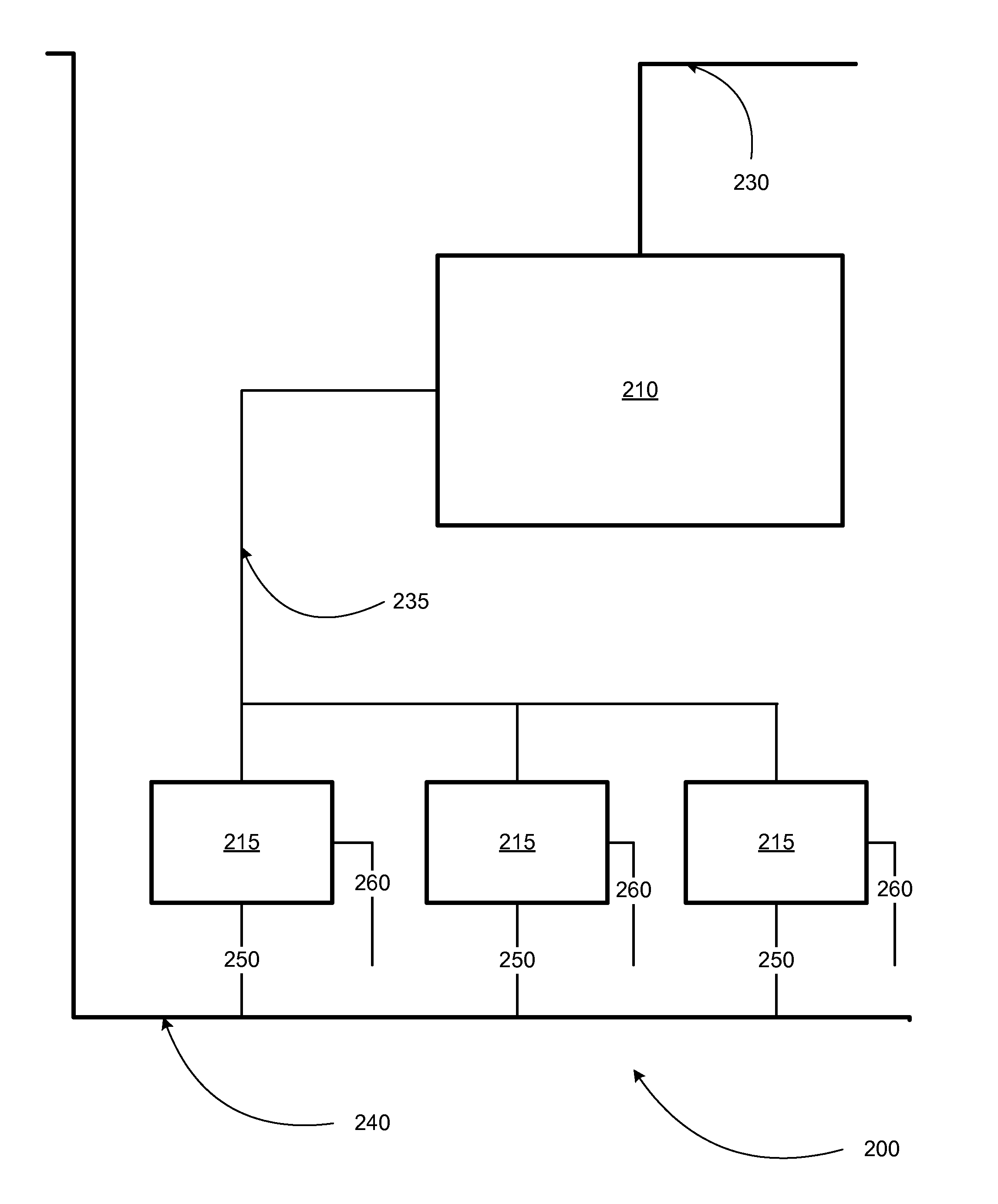
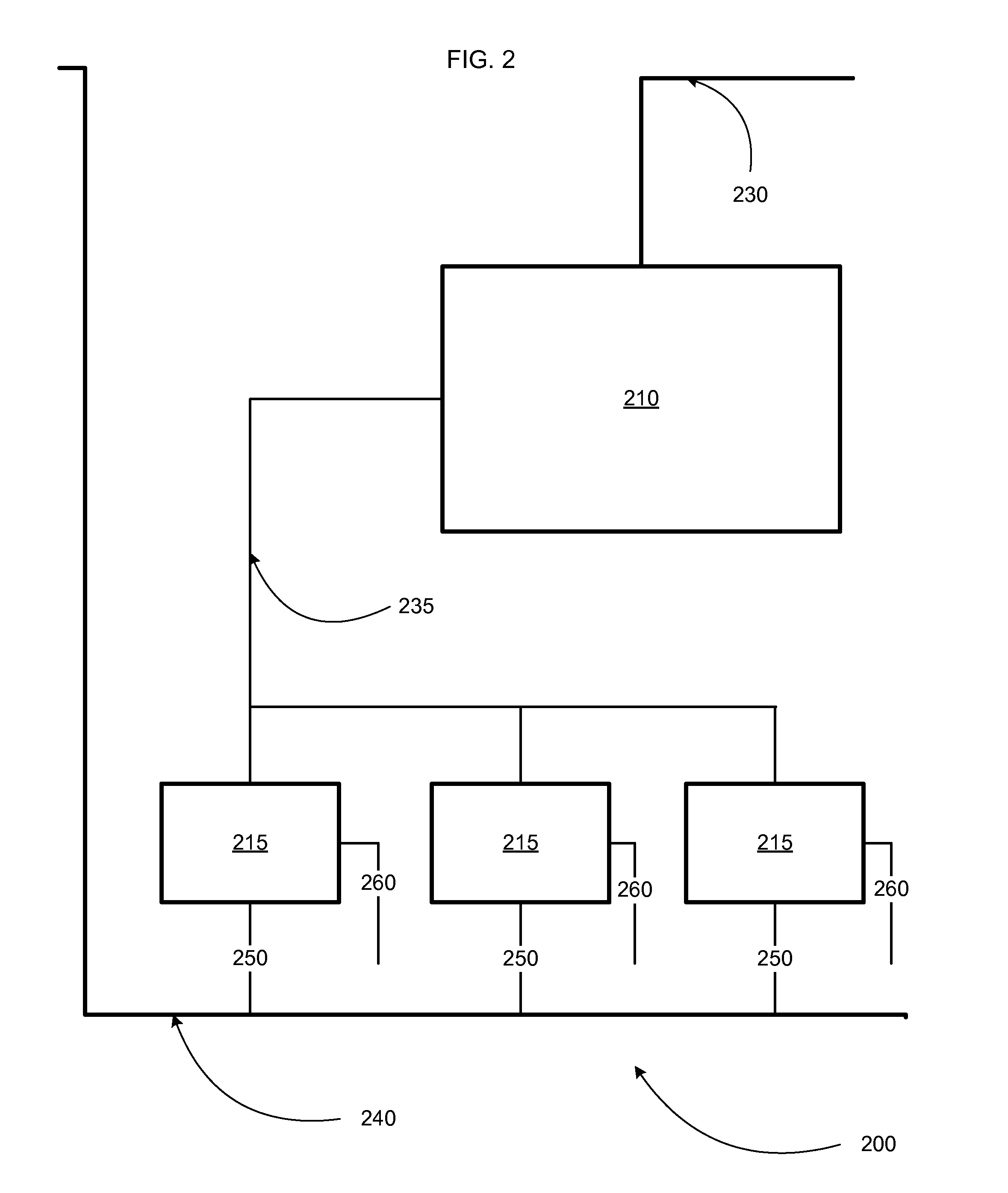
The patent describes a charge transfer apparatus for battery powered vehicles that can quickly charge them using a high power recharge level. The apparatus includes a generator, an AC / DC converter, and a DC transfer conduit. The generator produces electrical power at a high power level and decouples from the utility power grid. The AC / DC converter converts the electrical power to a direct current. The DC transfer conduit transfers the direct current to the vehicle's battery pack to recharge it. The apparatus can adjust the DC output based on operating parameters such as maximum and minimum battery capacity, and can also communicate data to the vehicle to prevent it from starting during charging. The apparatus can also include a primary mover and a fuel cell for power generation. The technical effects of the patent include quick charging capabilities for battery powered vehicles and improved efficiency of power transfer.

Problems solved by technology

Further, the amount of time required to fully charge a battery pack typically ranges between 4 to 8 hours.
In view of the recent increase in power outages due to increased load demands, line faults, and / or bad weather, it is evident that the current grid infrastructure will be unable to support such an increase in demand.
Further, the amount of power necessary to perform a quick charge, coupled with the reality of daily driving is likely to lead to increased power generation requirements during the peak demand periods.
Still further, assuming power generation capacity is increased to meet this demand, the increase in power demand is likely to require significant investment in the grid infrastructure.

Method used


Image

  • Recharging Electric Vehicles
  • Recharging Electric Vehicles
  • Recharging Electric Vehicles

Examples


Embodiment Construction

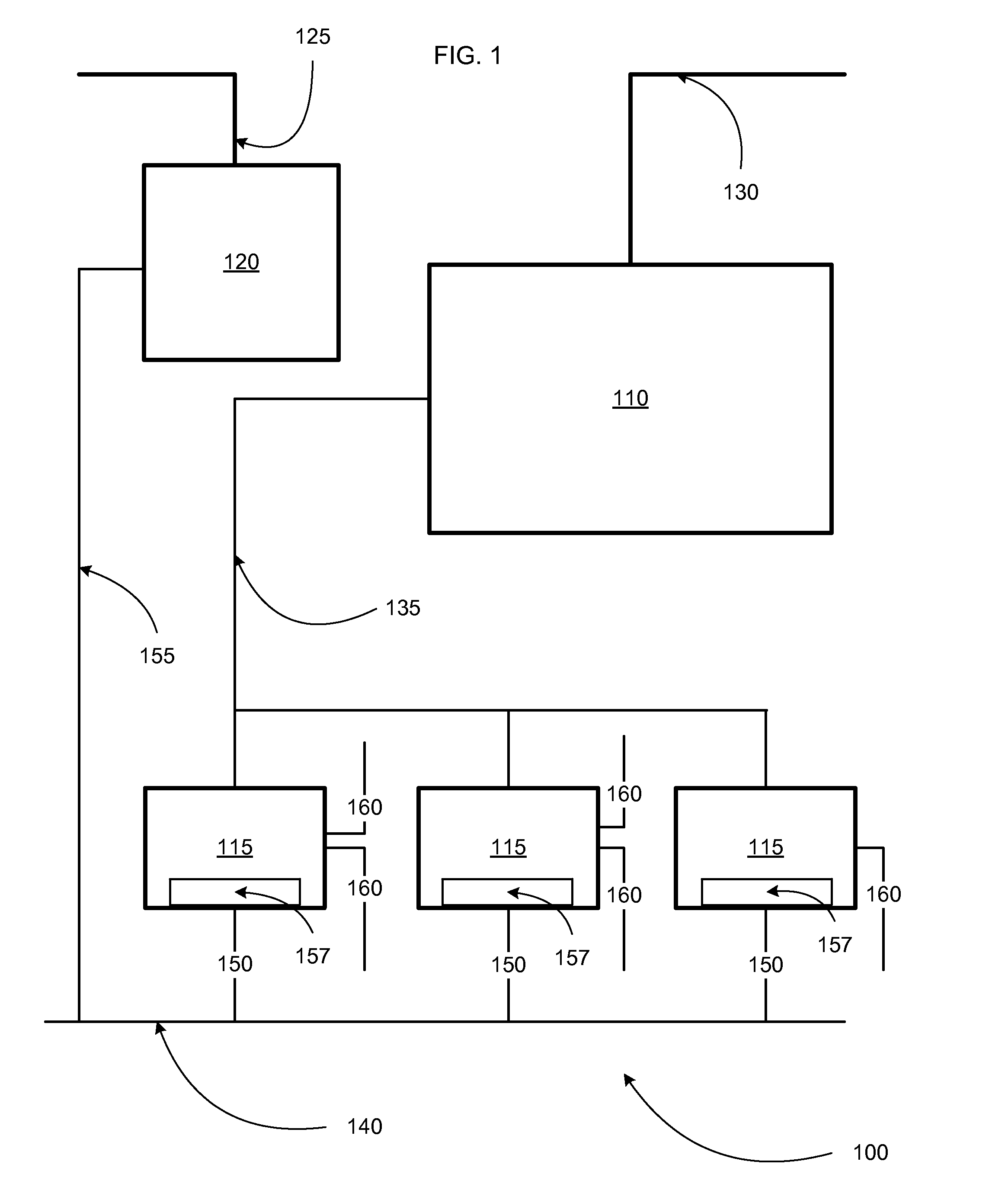
[0051]FIG. 1 is a block diagram illustrating one example embodiment of a fueling facility 100 operable to recharge an electric and / or hybrid vehicle (not shown) utilizing a facility power generator 120. Such a vehicle, for example, may be a parallel hybrid vehicle. For example, a parallel hybrid may include a battery and an electric motor / generator delivering power on a rotating shaft in parallel with a combustion engine delivering power in the more traditional fashion. Parallel hybrids often have better gas mileage, especially in urban traffic areas, in part due to brake energy used to run the motor as a generator to recharge the battery. Parallel hybrids may use gasoline, diesel, or ethanol. In addition, parallel hybrids may be light hybrids, or micro hybrids. For example, by replacing a belt driven alternator with a module serving as both the alternator and an assisting motor, gas mileage may be improved when the car is accelerating. For instance, used in conjunction with modern ...


PUM

PropertyMeasurementUnit
electrical currentaaaaaaaaaa
timeaaaaaaaaaa

Abstract

A charge transfer apparatus having an input and an output includes: an AC / DC converter coupled to the input of the charge transfer apparatus and configured to receive AC power at a first power level; and a charge storage device coupled to the AC / DC converter, where the charge storage device is configured to receive charge at the first power level and to transfer charge to the output of the charge transfer apparatus at a second power level, and the second power level is greater than the first power level.

Description

CLAIM OF PRIORITY[0001]This application claims priority under 35 U.S.C. §119(e) to U.S. Provisional Patent Application Ser. No. 61 / 261,248, filed on Nov. 13, 2009, the entire contents of which are hereby incorporated by reference.TECHNICAL BACKGROUND[0002]This disclosure relates to recharging electric and / or hybrid vehicles and, more particularly, to recharging electric and / or hybrid vehicles at a fueling facility through a dispenser.BACKGROUND[0003]Recent economic, environmental, and national security concerns have led to an increase in demand for more fuel efficient vehicles, and thus, less dependence on foreign oil and reduced carbon emissions. As a result, car manufacturers have incorporated a variety of technologies to improve gas mileage and / or reduce carbon emissions. One of the competing technologies in this space relies on the use of battery packs to provide power to an electric motor. A significant amount of research is currently being performed to improve the charge densi...

Claims


Application Information

Patent Timeline
Patent Type & Authority Applications(United States)
IPC IPC(8): H01M10/46H02J7/00
CPCB60L3/0046Y02T90/121B60L8/003B60L8/006B60L11/1824B60L11/185B60L11/1861B60L2210/10B60L2210/30Y02T10/7005Y02T10/7044Y02T10/705Y02T10/7083Y02T10/7241Y02T90/127Y02T90/128Y02T90/14Y02T10/7216B60L2200/26B60L3/04Y02T10/7072B60L53/11B60L58/12B60L53/305Y02T10/70Y02T10/72Y02T90/12Y02T90/16B60L53/30
Inventor OLSSON, MATS
Owner WAYNE FUELING SYST
Learn More