Electron beam apparatus

a technology of lithography apparatus and electron beam, which is applied in the direction of optical radiation measurement, instruments, therapy, etc., can solve the problems of small correction effect, inability to accurately correct for composite irradiation position error, and inability to accurately perform beam fluctuation correction. , to achieve the effect of high accuracy of beam fluctuation correction

Inactive Publication Date: 2011-05-19
NUFLARE TECH INC
View PDF22 Cites 7 Cited by
  • Summary
  • Abstract
  • Description
  • Claims
  • Application Information

AI Technical Summary

Benefits of technology

[0012]The present invention was made in view of the above facts, and an object thereof is to provide an electron beam lithography apparatus which can perform drawing while performing beam fluctuation correction highly accurately.

Problems solved by technology

Further, because an irradiation position error occurs due to a driving mechanism system for the stage, that is, a rotation drive and translation drive (feed drive) system for the stage on which a substrate is mounted, the mechanism system position error needs to be corrected for.
Thus, there is a problem that the correction effect is small since the correction is performed by feed-forward control.
Further, position errors due to the mechanism system are measured while drawing, and correction is performed by deflecting the electron beam based on the mechanism system position errors.
Conventionally, it is difficult to correct for this composite irradiation position error sufficiently accurately.

Method used


Image

  • Electron beam apparatus
  • Electron beam apparatus
  • Electron beam apparatus

Examples


first embodiment

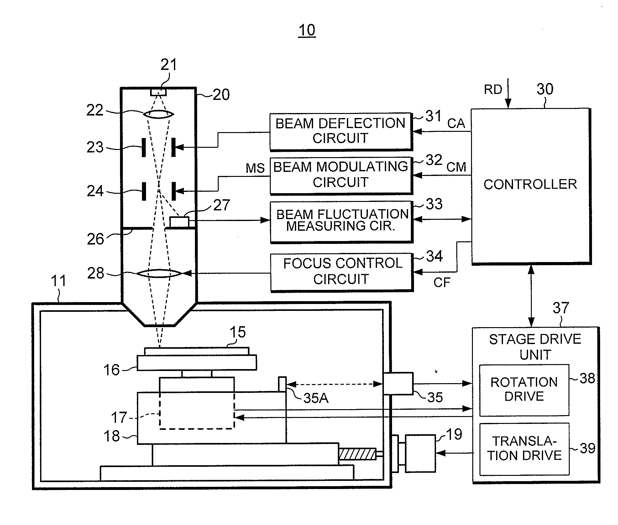
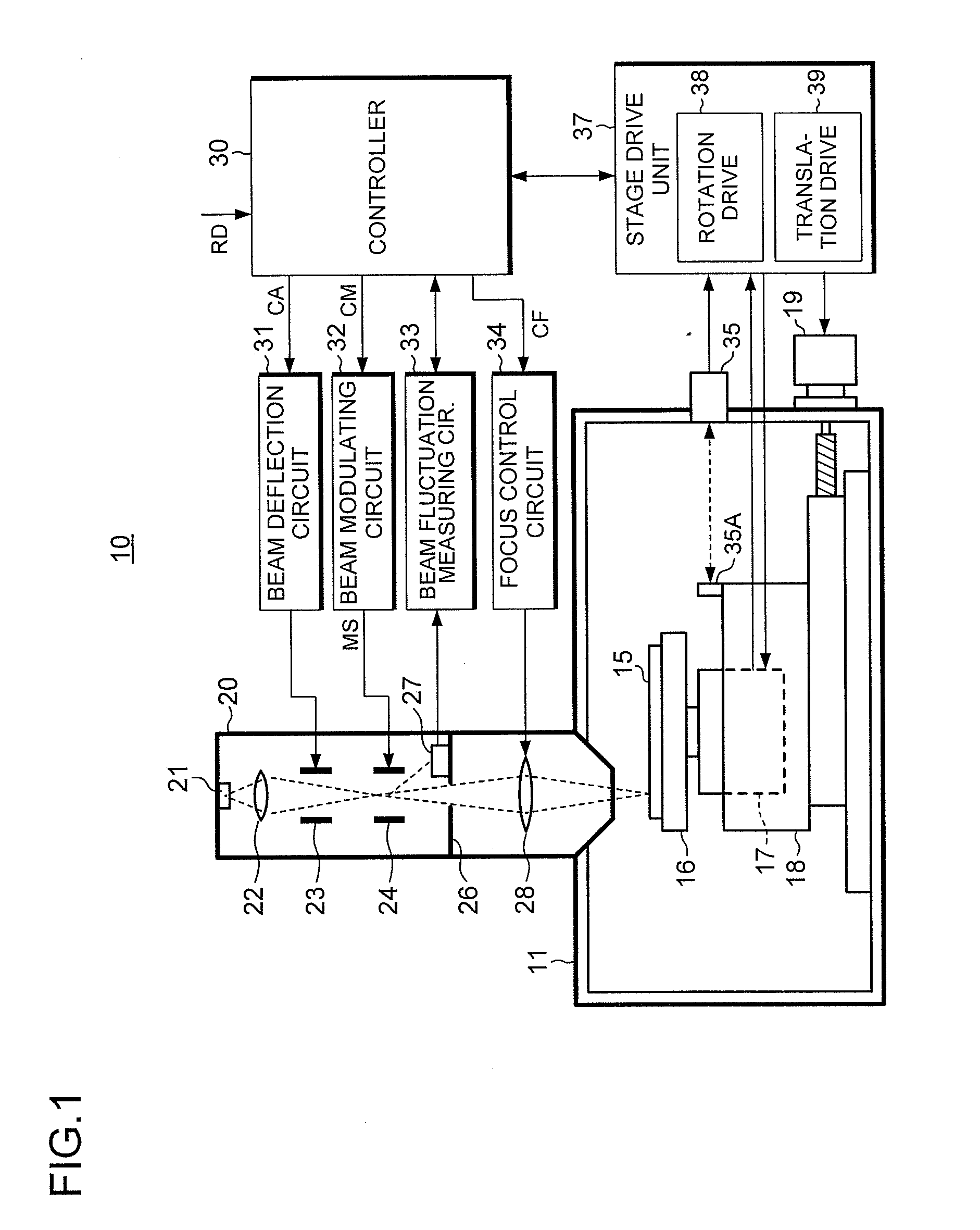
[0041]FIG. 1 is a block diagram showing schematically an example of the configuration of an electron beam lithography apparatus 10 according to a first embodiment of the present invention. The electron beam lithography apparatus 10 is a disc mastering apparatus which produces a disc master for the manufacture of optical discs or hard discs using an electron beam.

[Configuration and Operation of the Electron Beam Lithography Apparatus]

[0042]The electron beam lithography apparatus 10 comprises a vacuum chamber 11, a drive unit placed in the vacuum chamber 11 which has a substrate 15 mounted thereon and drives the substrate to rotate and move translationally, an electron beam column 20 mounted to the vacuum chamber 11, and a control system including various circuits for the drive control of the substrate, electron beam control, and so on.

[0043]More specifically, the substrate 15 to be a disc master has a resist coated over its surface, and is mounted on a turntable (or rotating stage) 1...


PUM


Abstract

An electron beam lithography apparatus includes a beam current detector which detects, during drawing of the drawing data, fluctuation of an irradiation position of the electron beam at non-irradiation on the substrate; a beam position error detector which detects a beam position error of the electron beam based on the fluctuation of the irradiation position; a drive position error detector which detects a drive position error of the stage due to rotation and translation drive during drawing of the drawing data; and a corrector which corrects the irradiation position of the electron beam during the drawing based on the beam position error and the drive position error.

Description

TECHNICAL FIELD[0001]The present invention relates to an electron beam apparatus and particularly to an electron beam lithography apparatus for producing a master of recording media or the like by electron beam exposure.BACKGROUND ART[0002]Electron beam lithography apparatuses that perform lithography using an electron beam as an exposure beam are widely applied to master producing apparatuses for optical discs such as digital versatile discs (DVDs) and Blu-ray discs and large capacity discs such as magnetically recording hard discs, and are also used in producing record media referred to as discrete track media or patterned media.[0003]When a master for the above-described discs or the like is produced using the electron beam lithography apparatus, a resist layer is formed on the recording surface of a substrate that is to become a master disc, and control is performed such that by making the substrate rotate and simultaneously move translationally so as to relatively move a beam s...

Claims


Application Information

Patent Timeline
Patent Type & Authority Applications(United States)
IPC IPC(8): H01J3/14
CPCG11B5/855G11B7/261H01J2237/30455H01J37/304H01J37/3023
Inventor KOBAYASHI, MASAKI
Owner NUFLARE TECH INC
Why Eureka
Try Eureka