Method of and apparatus for cleaning fouling in heat exchangers, waste-heat boilers and combustion chambers

a technology of waste heat boilers and cleaning methods, applied in the direction of steam boiler components, combustion process, combustion treatment, etc., can solve the problems of reducing the efficiency of heat exchangers, waste heat boilers, or combustion chambers

Inactive Publication Date: 2011-05-19
STEUR JR FRANS
View PDF39 Cites 0 Cited by
  • Summary
  • Abstract
  • Description
  • Claims
  • Application Information

AI Technical Summary

Benefits of technology

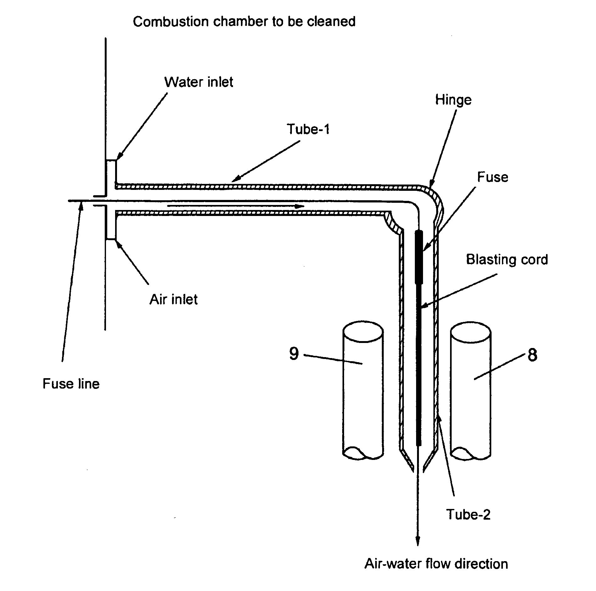
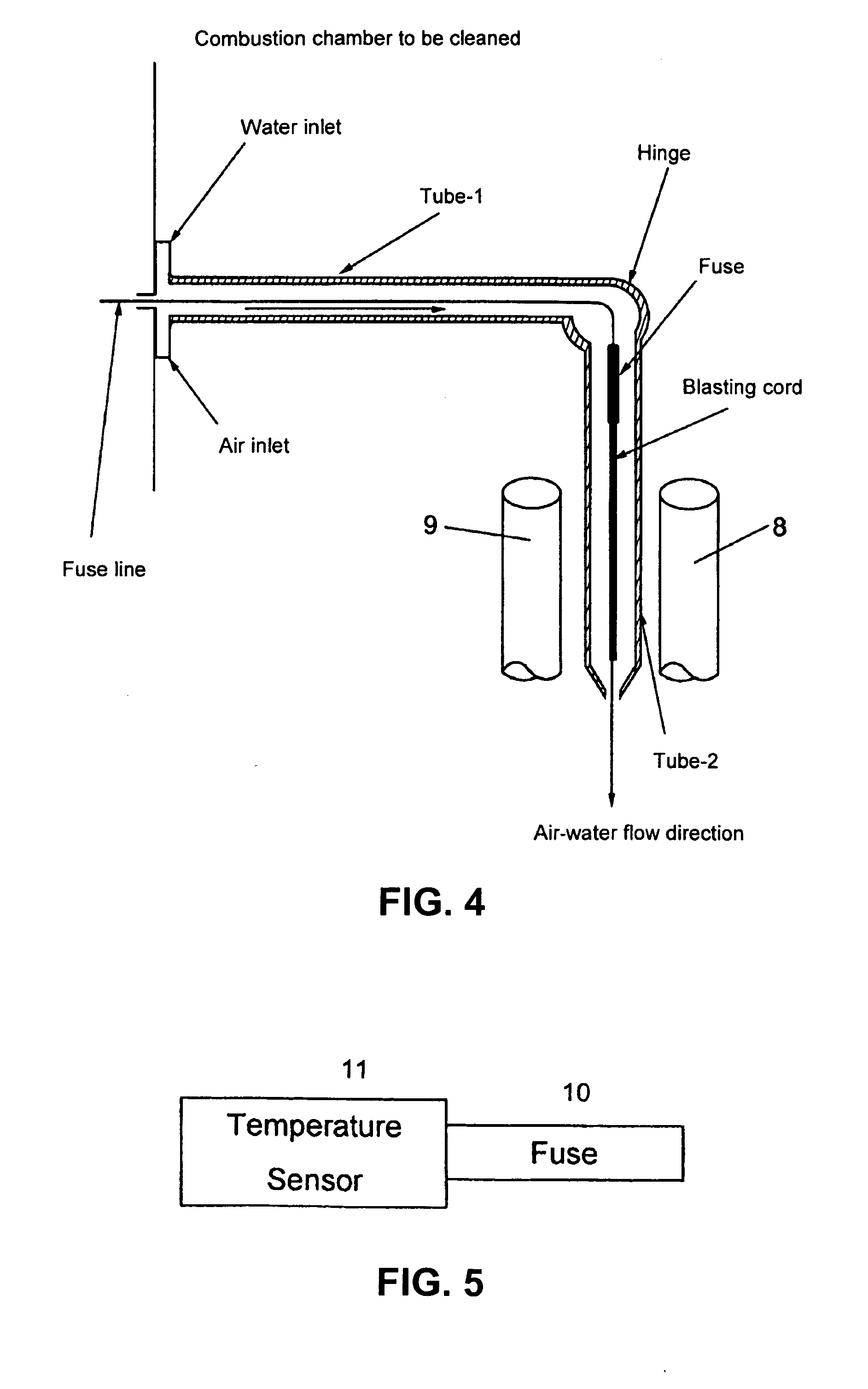
[0004]Disclosed herein is a device for cleaning contamination in a heat exchanger apparatus, a heat boiler apparatus, or combustion chamber. In some embodiments, the device permits cleaning of contamination in a space to be cleaned that is below room temperature, or below 100° C. In some embodiments, the device allows the detachment of more than a small part of pollutants and contaminating material which are applied externally to the lines or inside walls of the space to be cleaned, and / or some of any contaminating material and pollutants which are disposed between the tubes or, as viewed from the explosion point, behind the tubes. In some embodiments, the device comprises a long tube with a relatively small diameter wherein a combustible gas mixture and / or a blasting body is provided within the tube, and the tube is destroyed after blasting. In some embodiments, the device comprises a first tube and a second tube, wherein the second tube is connected to the first tube by a hinge, and wherein the second tube contains a fuse connected to blasting cord.
[0005]The device is capable of effecting a linear blasting process (as opposed to a ball-shaped blasting process), wherein the blasting effect is distributed over a great length. Thus, in some embodiments, a tube (e.g., a tube of cardboard and / or copper) may be filled with a gas mixture, and / or provided with a blasting cord on the inside of the tube, so that a desired blasting effect can be achieved by the blasting process. An explosion in accordance with the invention may generate a shock wave that removes polluting contamination from a heat exchanger. In some embodiments, a small tube diameter allows cleaning between contaminated lines or bundles of lines. And, if a coolant is flowing through the blasting tube, the cleaning operation may take place when the temperature within the combustion chamber of the heat exchanger has not yet fallen very far (for example, during operation of the heat exchanger, or after the heat exchanger has been shut down for a short time). Thus, in some embodiments, long periods during which the heat exchanger must be shut down for cleaning (for example, periods up to several days) may be avoided.

Problems solved by technology

The gathering of soot and / or combustion residues ultimately reduces the level of efficiency of the heat exchanger, waste heat boiler, or combustion chamber.
For example, a textile bag is filled with a gas mixture outside the space to be cleaned, introduced into the space that is to be cleaned, and caused to explode therein.
However, since the lines that carry the medium to be heated are often very close together, the blasting effect can detach only a small part of the pollutants and contaminating material that are applied externally to the lines or inside walls of the space to be cleaned, but frequently not any of the contaminating material and pollutants that are disposed between the tubes or, as viewed from the explosion point, behind the tubes.

Method used


Image

  • Method of and apparatus for cleaning fouling in heat exchangers, waste-heat boilers and combustion chambers
  • Method of and apparatus for cleaning fouling in heat exchangers, waste-heat boilers and combustion chambers
  • Method of and apparatus for cleaning fouling in heat exchangers, waste-heat boilers and combustion chambers

Examples


Embodiment Construction

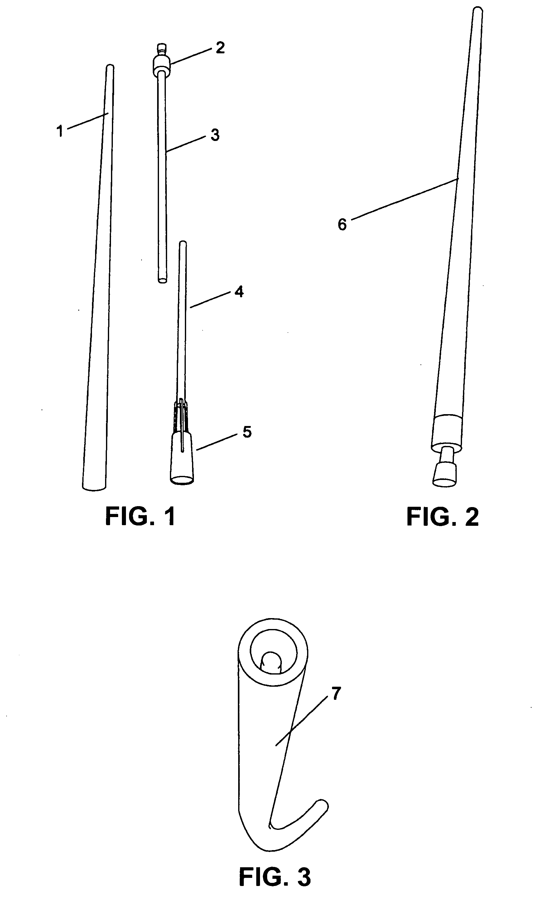
[0007]FIG. 1 shows a cardboard tube 1, which accommodates a spark plug 2. The tube is provided at one end with a closure means, and a gas filling connection 5 is provided at the other end.

[0008]FIG. 2 shows an assembled embodiment 6 of the device.

[0009]Depending on the desired use, the tube can be made of any length. For example, in the embodiment depicted in FIG. 2, the tube is of a relatively small diameter (e.g., 3 cm to 15 cm), so that the tube may be introduced into a heat exchanger line containing gases within a combustion chamber.

[0010]After triggering of a blasting action that may destroy the entire cardboard tube, certain parts, such as a spark plug, threaded rod, closure means, and so forth, can be further used again.

[0011]FIG. 3 shows an alternative embodiment, wherein a first tube, which is connected to a second tube via a hinge 7, is fitted into a combustion chamber. Due to the hinge 7, the angle of the second tube (blasting tube) can be precisely adjusted according to ...


PUM


Abstract

A device for cleaning contamination in heat exchangers, waste-heat boilers, or combustion chambers is provided. In some embodiments, the device comprises a tube, a blasting body, and a combustible gas mixture within the tube. In some embodiments, the tube is destroyed after blasting. In some embodiments, the device further comprises a second tube comprising a blasting cord that is connected to a fuse, wherein the second tube is coupled to the first tube by a hinge.

Description

CROSS-REFERENCE TO RELATED APPLICATION[0001]This application is a continuation of U.S. patent application Ser. No. 11 / 142,565, filed Jun. 1, 2005, pending, the disclosure of which is hereby incorporated herein by this reference in its entirety.BACKGROUND[0002]It is generally known that heat exchangers, waste-heat boilers, and combustion chambers (i.e., spaces in which combustion takes place which are provided with lines through which flows a medium to be heated) have to be cleaned at certain time intervals. The reason such cleaning becomes necessary is that the lines through which flows a medium to be heated gather soot on their outsides due to the combustion process within the combustion chamber, or else become covered by a layer of combustion residues that impede or prevent the transfer of heat. The gathering of soot and / or combustion residues ultimately reduces the level of efficiency of the heat exchanger, waste heat boiler, or combustion chamber.[0003]“Explosion cleaning proced...

Claims


Application Information

Patent Timeline
Patent Type & Authority Applications(United States)
IPC IPC(8): F28G11/00F28G1/12
CPCB08B7/0007F28G7/005F28G7/00F23J3/02
Inventor STEUR, JR., FRANS
Owner STEUR JR FRANS
Why Eureka
Try Eureka