
Method of applying multiple materials with selective laser melting on a 3D article

Inactive Publication Date: 2011-05-05
ANSALDO ENERGIA IP UK LTD
View PDF68 Cites 87 Cited by
  • Summary
  • Abstract
  • Description
  • Claims
  • Application Information

AI Technical Summary

Benefits of technology

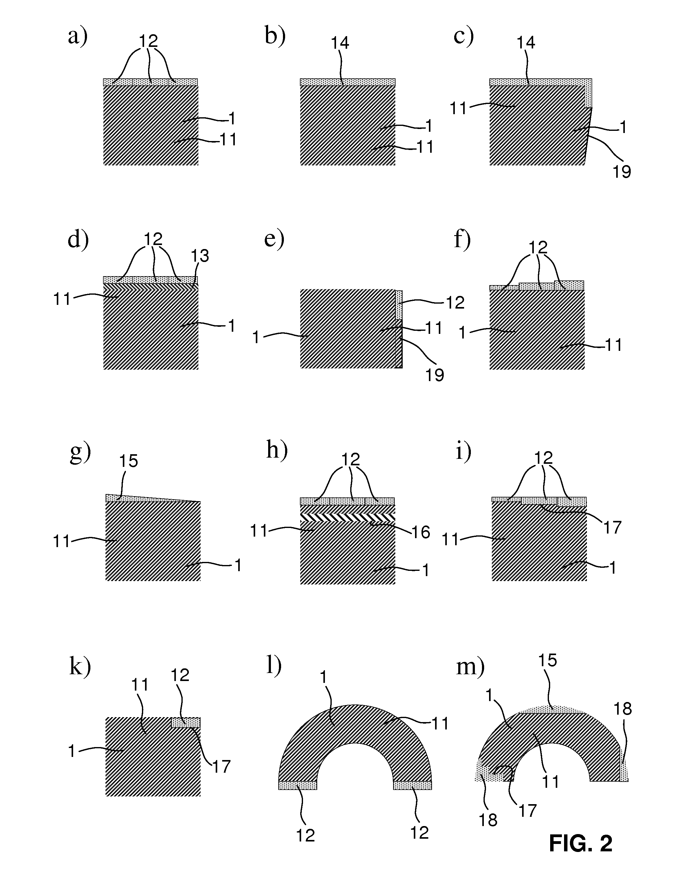
Another aspect of the present invention includes a method to use foils / tapes / sheets instead of powder for a second and any additional material different from the previous (powder based) to be applied. These foils / tapes / sheets can be used, e.g., for the application of abrasive materials or hardface materials and can be applied on different sections / portions (e.g., on edges) of the 3D article. A different material can also be applied on contact faces to improve the heat transfer. An improvement of the welding quality can also be achieved.
Among other potential benefits, one important benefit is the avoidance of the powder bed contamination when using foils / tapes / sheets instead of different powder material for the application of a different material on specific sections / portions of the part to be manufactured. Thus, the expensive powder in the powder bed can be reused for another application on the same or a different part.
The second material can, for example, be applied to contact faces to increase the weld ability / brazeability and / or to facilitate a joint to another three-dimensional article, for example, to a single crystal or a directional solidified article.
One particular potential advantage of methods embodying principles of the present invention is not only the independence of a metallic powder bed, but also the fact that the three-dimensional shape of pre-forms used can be adapted and tailored. This adaptation is possible in the sense as to define a target outer shape of the article by providing a specifically three-dimensionally pre-form of the second material. On the other hand, the pre-form can be structured in a complementary manner to the contact face of the article at the place where the pre-form is to be applied. Also combinations of these two shapes, so a complementary adaptation to the outer form of the article prior to the application of the pre-form and a three-dimensional structure in the outer side to define the outer shape of the final article after the step of application the pre-form, is possible. This shows the tremendous versatility of methods in accordance with principles of the present invention.
Advantages of the methods described herein include, for example:Application of multiple, different materials without contamination of the powder in the powder bed. The expensive powder can be reused.There is no need of process combinations and therefore, besides a handling device, no other process equipment is required.Cost reduction.Flexibility and productivity improved.Simplified handling.Increase of product functionality.

Problems solved by technology

One of the problems associated with these methods is the delivery of the powder for the individual steps.
In order to apply a second material (different metal powder), the first material has to be removed completely with great efforts or the powder bed is contaminated.
Possible methods and devices to locally remove previously deposited first material powder with a suction or blow-off device are expensive, slow and may not avoid powder contamination.
Therefore the layer-wise powder SLM process can not efficiently be used for this task and a laser generating process such as DMD (Direct Metal Deposition) / LENS (Laser Engineered Net Shape) has to be integrated.

Method used


Image

  • Method of applying multiple materials with selective laser melting on a 3D article
  • Method of applying multiple materials with selective laser melting on a 3D article
  • Method of applying multiple materials with selective laser melting on a 3D article

Examples


Embodiment Construction

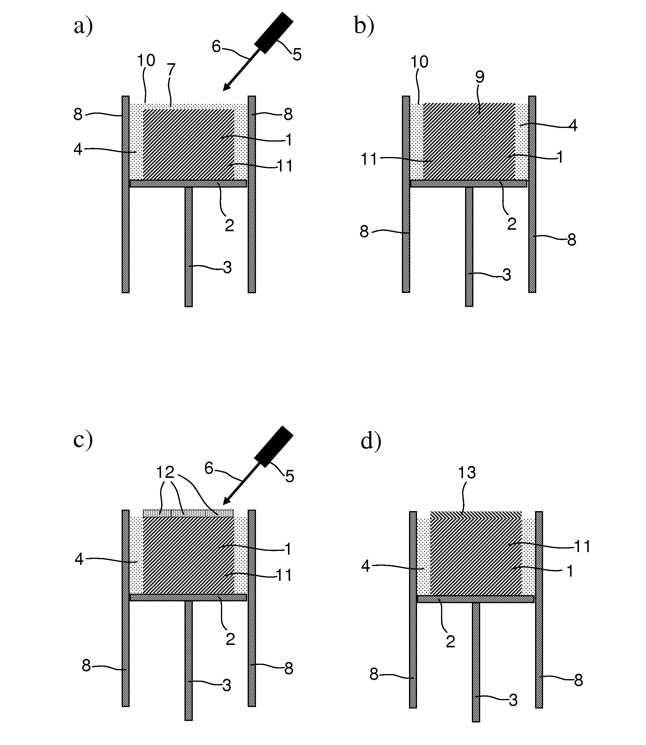
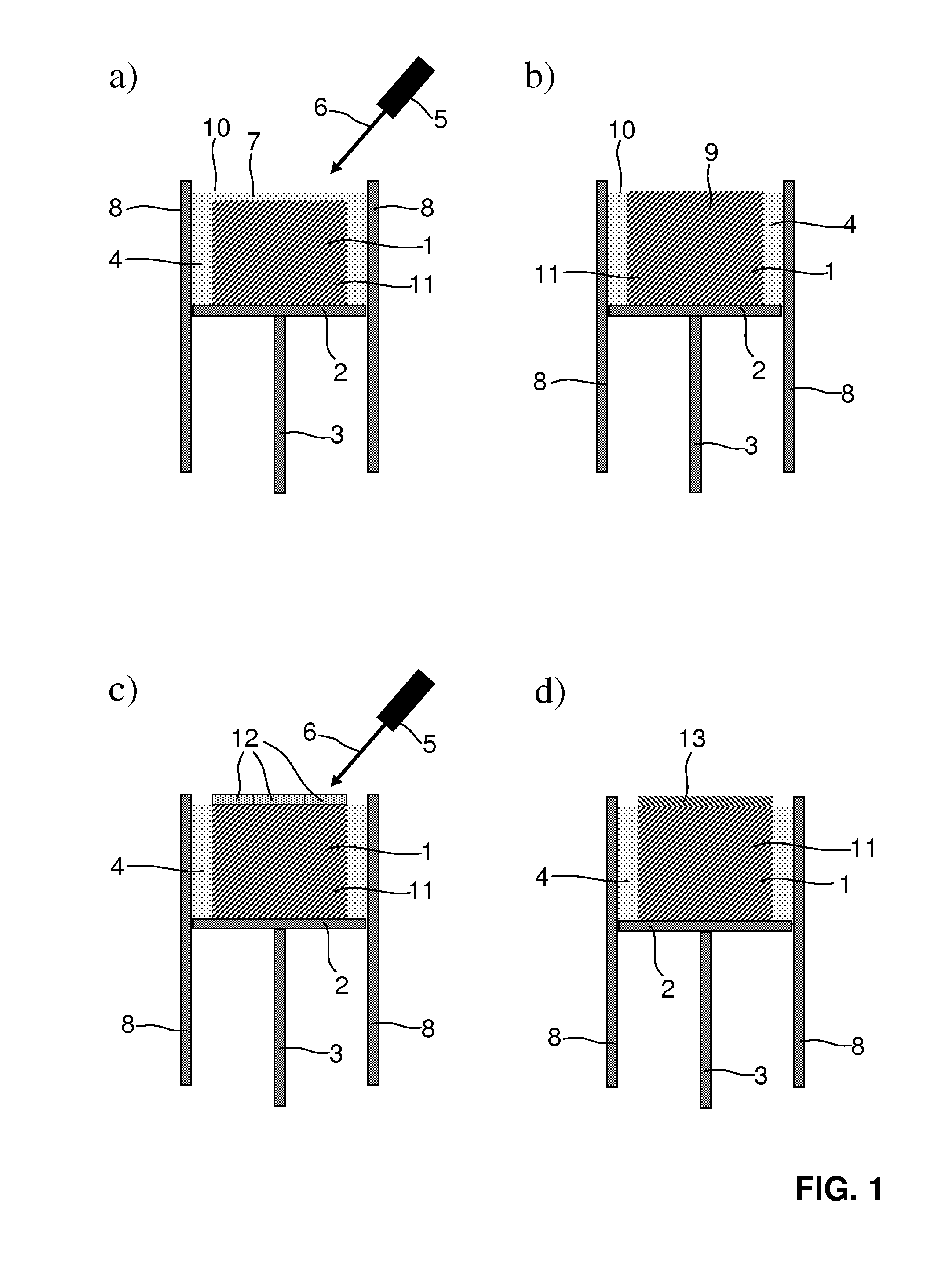
In FIG. 1 a sequence of the production steps using a method embodying principles of the present invention is shown. FIG. 1a schematically illustrates the basic set up of a metal powder based selective laser melting (SLM) or direct metal laser sintering (DMLS) or electron beam melting (EBM) process. In this process, according to the state of the art processes, an article with a three dimensional shape 1 is consecutively built up layer by layer in a metal powder bed 4.

The metal powder bed 4 is present in a cavity enclosed by side walls 8 in which typically a support platform 2, for example by a vertical bar 3, is mounted such as to be vertically displaceable. With respect to the general principles of such a process, reference is made to the disclosure of WO 92 / 10343 as well as to the one of WO 98 / 24574.

FIG. 1a shows the situation just prior to the deposition of yet another layer of material on a block of first material 11 already solidified by preceding laser melting steps. In the pro...


PUM

PropertyMeasurementUnit
Lengthaaaaaaaaaa
Thicknessaaaaaaaaaa
Thicknessaaaaaaaaaa

Abstract

In a method for manufacturing an article (1), particularly a prototype of a product or component, a tool prototype or spare part, by using selected laser melting, for the application onto the article (1) of a layer (13) or portion of a second metallic material, which is different from the material of the first metallic powder (4), a tape (12), sheet (14), foil or three-dimensional pre-form (18) of a second material is applied to the article (1) and is heated by a focused laser or electron beam (6) to a specified temperature such that the tape (12), sheet (14), foil or pre-form, respectively, are made molten by the electron laser beam (6), wherein the focused beam (6) is applied to a given area corresponding to a selected cross-sectional area of the model of the article (1) under formation of a new layer or part made of second material integral with the article (1).

Description

BACKGROUND1. Field of EndeavorThe present invention relates to methods of applying multiple different materials with selective laser melting on a 3D article as well as to 3D articles, in particular turbine components and parts thereof.2. Brief Description of the Related ArtMethods for manufacturing a molded body, e.g., a prototype of a product or component, a tool prototype or spare part, in accordance with three-dimensional CAD data of a model of a molded body, by depositing layers of a liquid material or a metallic material in powder form, have become increasingly popular and commercially important.One of these methods is known as stereo lithography. In stereo lithography, a molded body to be manufactured is divided into individual layers and the data of the individual layers concerning the prototype to be manufactured are supplied to a manufacturing device. Such a manufacturing device consists of a liquid bath with a UV hardening liquid that a UV beam sweeps over according to the...

Claims


Application Information

Patent Timeline
IPC IPC(8): G06F17/00
CPCB22F3/1055B22F5/009B22F5/04B22F7/062B22F7/08B22F2999/00B22F3/1035Y02P10/25B22F10/28B22F10/43
Inventor HOVEL, SIMONESTANKOWSKI, ALEXANDERRICKENBACHER, LUKAS
Owner ANSALDO ENERGIA IP UK LTD
Learn More