
Methods of synthesis and use of chemospheres

a chemosphere and synthesis technology, applied in the field of synthesis and use of chemospheres, can solve the problems of maximizing the time of drug release, burst release of therapeutic agents, and inability to readily phagocytize liposome polymer matrices, and achieve the effect of preventing immunoclearan

Inactive Publication Date: 2011-05-05
THE JOHN HOPKINS UNIV SCHOOL OF MEDICINE
View PDF12 Cites 165 Cited by
  • Summary
  • Abstract
  • Description
  • Claims
  • Application Information

AI Technical Summary

Benefits of technology

[0013]The experiments described herein demonstrate that the combination of polymer and liposome has an unexpected effect of synerginicity in which compound is released slower from a polymer / liposome matrix at a far reduced rate as compared to a polymer or liposome.
[0111]In another embodiment, the nanoparticles are coated with dextran, peg or another agent that increases biocompatibility. In a further embodiment, the particle is an iron oxide. In another embodiment, the particle is feridex.

Problems solved by technology

Alone, these polymers when loaded with small mw therapeutic agents result in a burst release of therapeutic agents.
Though pegylating liposomes has served to increase circulating time of liposomes, the liposome polymer matrices can not be readily phagocytized and thus can persist for extended periods in the body thereby maximizing the time of drug release.

Method used


Image

  • Methods of synthesis and use of chemospheres
  • Methods of synthesis and use of chemospheres
  • Methods of synthesis and use of chemospheres

Examples


example 1

Methods of Preparation of Embolization Particles

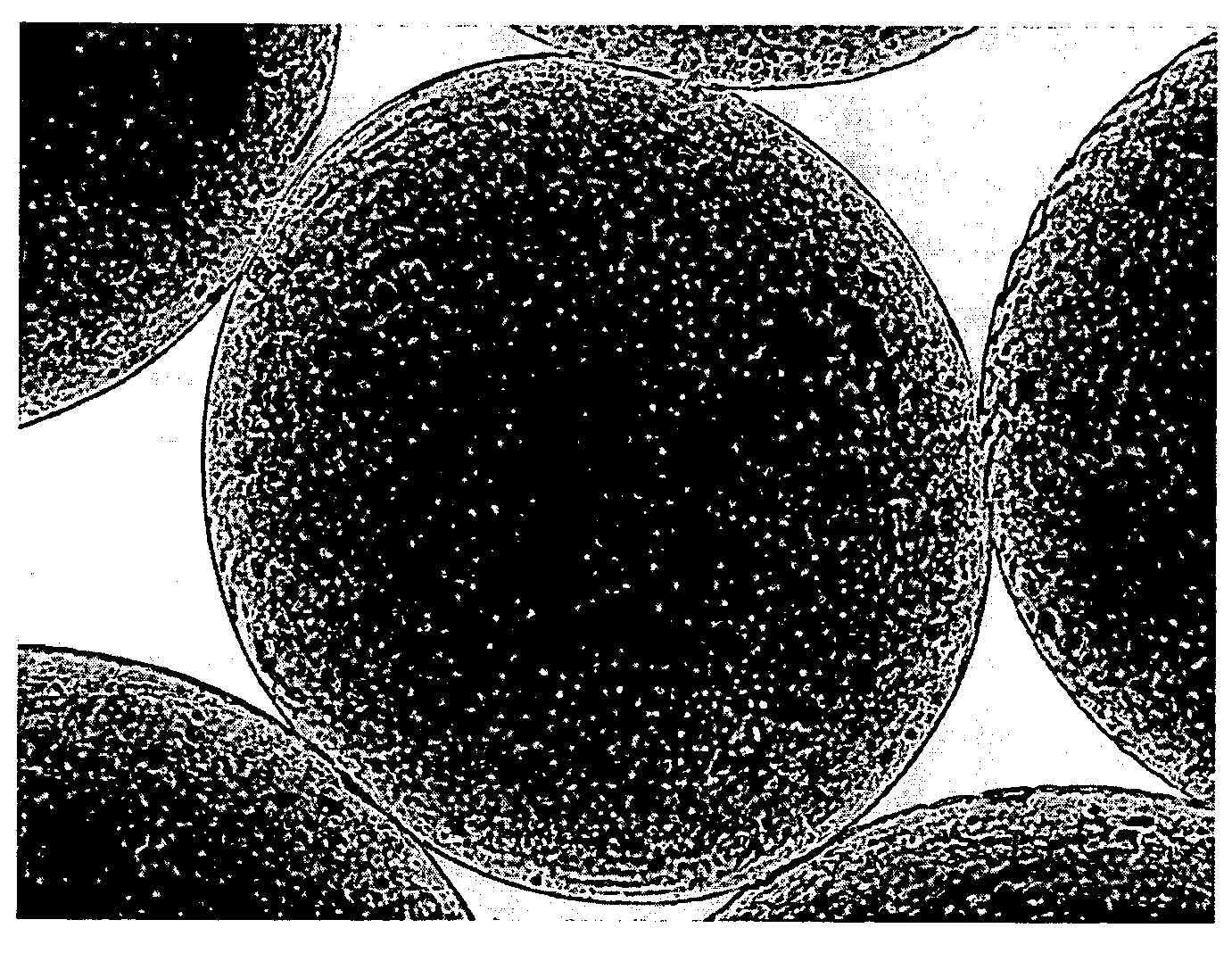
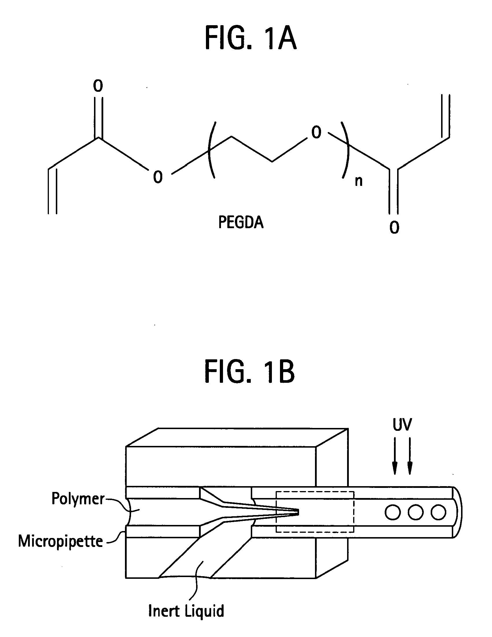
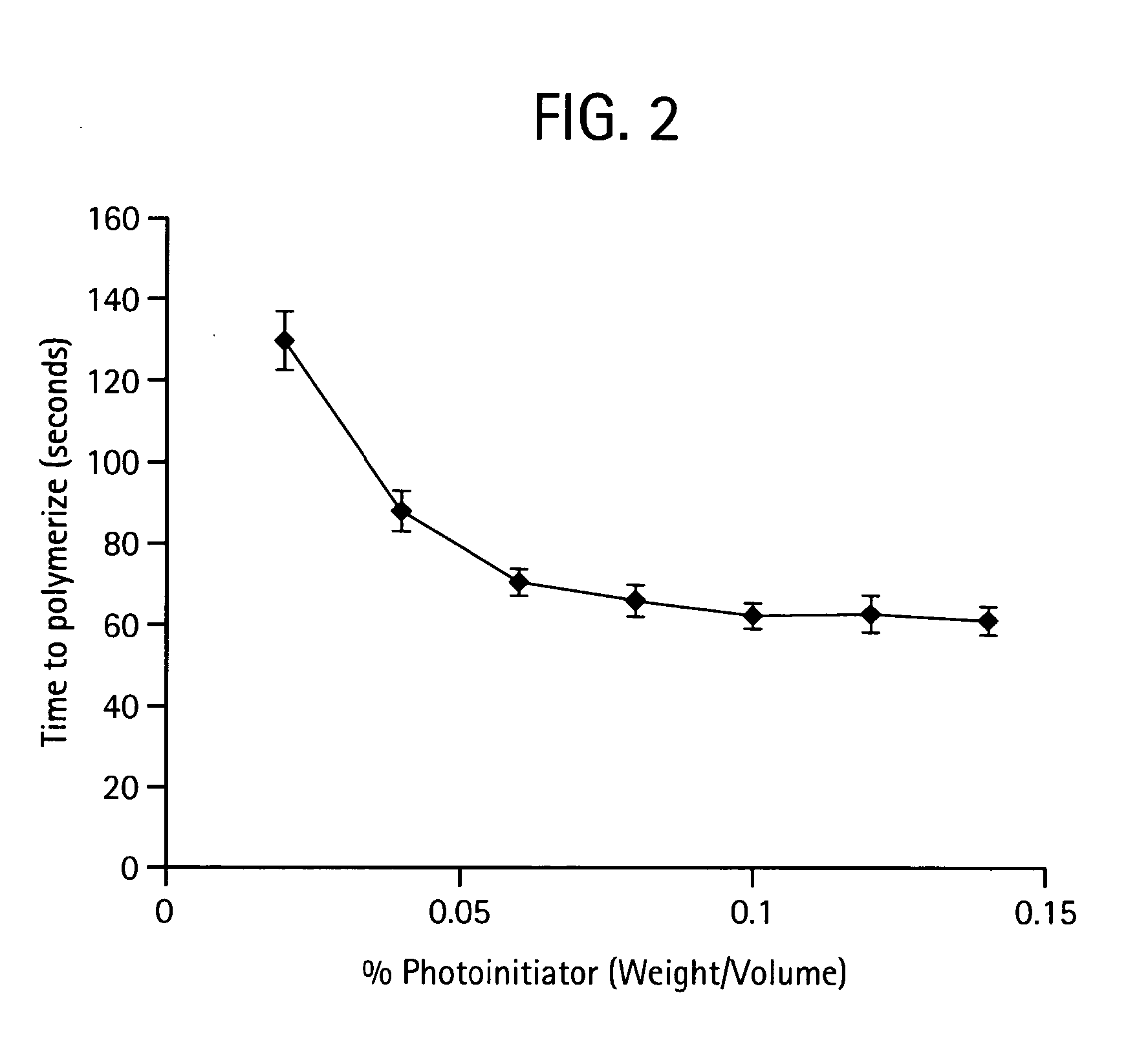
[0562]In a preferred embodiment a polymer is prepared by mixing poly(ethylene glycol)-diacrylate (PEGDA; Nektar Therapeutics, Huntsville, Ala.) in sterile phosphate-buffered saline (PBS; GIBCO Invitrogen, Carlsbad, Calif.) to make a 15% (w / v) hydrogel. Photoinitiator, Igracure D2959 (Ciba Specialty Chemicals, Tarrytown, N.Y.) is added to the polymer at a concentration of 0.05% (w / v). The mixture is then added drop-wise to a reactant medium made up of an inert bath. An inert bath includes but is not limited to a formulation of 160 grams Span 80 and 3,840 grams USP mineral oil. The inert bath is then stirred at a rate of 200 RPM in a reaction vat. The Vat was then exposed to UV irradiation to initiate polymerization. Once reacted, the resultant crosslinked PEGDA sphere were cleaned of mineral oil and Span 8. The cleaning process involved dumping the resultant spheres over a 45-micron screen such that the beads were trapped on the screen ...

example 2

Methods of Preparation of Embolization Particles

[0563]In an alternate example, embolization particles were made using a slightly different process. The same procedure as above was followed, but the rpm of the reaction medium was increased to 300 rpm. The resulting particles exhibited the same mechanical properties as the spheres as described in Example 1, but the average size of these particles was smaller than the average size of the particles made according to the methods described in Example 1. Without being limited by theory, it is believed based on these results that the rpm of the reaction medium can be manipulated to obtain desired particle sizes.

example 3

Methods of Preparation of Embolization Particles

[0564]In this example, embolization particles were made using a slightly different process. The same procedure as in Example 1 was followed, but a van de graaf generator was attached via an insulated wire to the tip of the needle extruding the pegda solution. The inert bath was grounded by placing an insulated wire that was attached to an external ground in the bath. With the bath grounded the van de graaf generator was turned on thereby creating an electrostatic charge between the needle tip and the inert bath. Without being limited by theory, it is believed that the electrostatic potential between the needle tip and inert bath causes PEGDA droplets to fall into the bath at a smaller size.


PUM

PropertyMeasurementUnit
bioactiveaaaaaaaaaa
metallicaaaaaaaaaa
radioactiveaaaaaaaaaa

Abstract

The present invention provides, in general, compositions comprising a hydrogel and an agent, for example a therapeutic agent or an imaging agent, for locoregional delivery. In certain preferred embodiments of the invention, the hydrogel compositions are detectable by Magnetic Responance and CT Scan and are used for locoregional delivery of therapeutic agents, for example chemotherapeutic agents. The invention also features polymer matrix compositions comprising nanoparticles that can be loaded after polymerization with bioactive agents, for example a diagnostic agent or therapeutic agent.

Description

PRIORITY[0001]This application claims priority to U.S. Provisional Application No. 61 / 005,228, as filed on Dec. 3, 2007, and to U.S. Provisional Application No. 61 / 093,619, as filed on Sep. 2, 2008. The disclosures of both Applications are incorporated herein by reference in their entireties.INCORPORATION BY REFERENCE[0002]Each of the applications and patents cited in this text, as well as each document or reference cited in each of the applications and patents (including during the prosecution of each issued patent; “application cited documents”), and each of the PCT and foreign applications or patents corresponding to and / or paragraphing priority from any of these applications and patents, and each of the documents cited or referenced in each of the application cited documents, are hereby expressly incorporated herein by reference. More generally, documents or references are cited in this text, either in a Reference List, or in the text itself; and, each of these documents or refe...

Claims


Application Information

Patent Timeline
Patent Type & Authority Applications(United States)
IPC IPC(8): A61K51/12A61K9/14A61K49/18A61K35/12A61K39/395A61K9/127A61P7/04A61P35/00A61K31/704B82Y5/00
CPCA61K9/0019A61K9/0051A61K9/06A61K9/127A61K9/1271A61K9/1617A61K49/1824A61K9/1652A61K9/19A61K31/00A61K31/4745A61K31/704A61K47/32A61K9/1635A61P35/00A61P7/04
Inventor BARNETT, BRADLEY POWERSGESCHWIND, JEFFREY
Owner THE JOHN HOPKINS UNIV SCHOOL OF MEDICINE
Learn More