
Ceiling fire extinguishing system with lost air filtration - the ceiling firefighter™

a fire extinguishing system and ceiling firefighter technology, applied in fire rescue and other directions, can solve the problems of putting the operator in danger of exposure to smoke and flames, the failure of the sprinkler system, and becoming an electrical hazard for both trapped occupants of the building, so as to improve the air quality of the building, reduce structural damage, and increase the possibility of life saving events

Inactive Publication Date: 2011-05-05
DICKENS SR JAMES DANIEL +1
View PDF5 Cites 2 Cited by
  • Summary
  • Abstract
  • Description
  • Claims
  • Application Information

AI Technical Summary

Benefits of technology

[0025]This invention relates to ceiling tile system used as a method of mechanical fire extinguishing, energy conservation, and air filtration for improved air quality of buildings, within a restricting of the conventional ceiling systems of buildings. The intended use of the ceiling system is designed as a side by side function with attic sprinkler systems or as a stand alone fire extinguishing system. This invention's purpose is to increase the possible life saving events under building fire situations, and reduce structural damage caused by building fires.BACKGROUND
[0027]The object of the invention is to overcome at least some of the drawbacks related to current attic installed sprinkler systems such as fuel induced fires, electrical hazards, and supply requirements. As a secondary function to provide improved air quality with its construction materials of a porous nature thus capturing the use of climate control leaks of air handling systems. Finally, the invention provides additional function to conserve energy within the building as well, due to the nature of the granulated fire retardant would also restrict the conduction of thermal transfer, thus improving the performance of air conditioning and central heating systems within buildings.

Problems solved by technology

Canister extinguishing systems require a hand held function thus operating these extinguishes in close proximity of the flames of a fire, putting the operator in danger of exposure to smoke and flames.
(a) They require a continual supply of pressure bearing water. If the supply of water is breached the sprinkler system fails to operate, as witnessed in the World Trade Center on 911.
(b) Sprinkler systems currently have two methods to trigger the water action, either a lead metal trigger that requires enough flame heat to melt the lead trigger, or a smoke sensitive trigger to activate the water based sprinkler action.
(c) The sprinkler action of water dispersed along with compromised electrical systems during a fire can become an electrical hazard to both trapped occupants of a building, and for emergency response personnel.
(d) Mounting brackets for Sprinkler systems can become compromised and fall from the ceiling creating a hazard to occupants and emergency response personnel.
(e) Water supplied sprinkler systems are ineffective against lighter by weight than water, fuel activated flames.
(f) Sprinkler systems that are damaged can cause expensive damage and clean up costs.
(h) Sprinkler systems are expensive to install and maintain.
(a) At best, they only slow the spread of fire.
(b) Many still have asbestos media, which has been the subject of expensive legal action for the health hazards such asbestos media produces.
(c) They cause more smoke during a fire.
(d) They do little to save lives.
(e) They do little to save property.
Given that the existing fire extinguishing systems such as canister hand held extinguishes require a person to often be in harms way of flames in order to operate them.
Sprinkler systems also present additional hazards and limitation to complete function of flame extinguishing.

Method used


Image

  • Ceiling fire extinguishing system with lost air filtration - the ceiling firefighter™
  • Ceiling fire extinguishing system with lost air filtration - the ceiling firefighter™

Examples


Embodiment Construction

[0032]The Ceiling Firefighter invention will be described herein with reference to the accompanying drawings, in which evidence of the embodiments of the invention are illustrated. While this invention may be embodied in many different forms and should not be construed as limited to the embodiments set forth in this description; rather, these embodiments are provided by way of examples so that this disclosure will satisfy applicable legal requirements. Thus numbers will refer to like elements throughout.

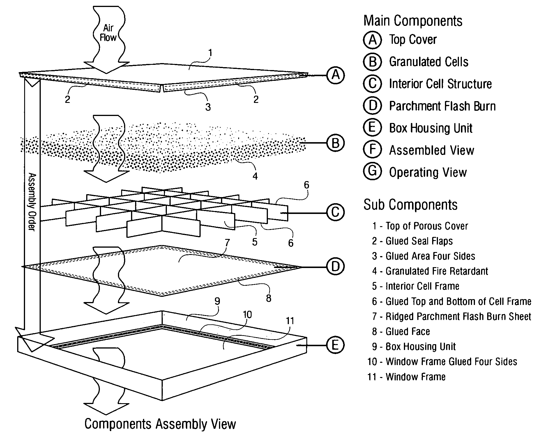
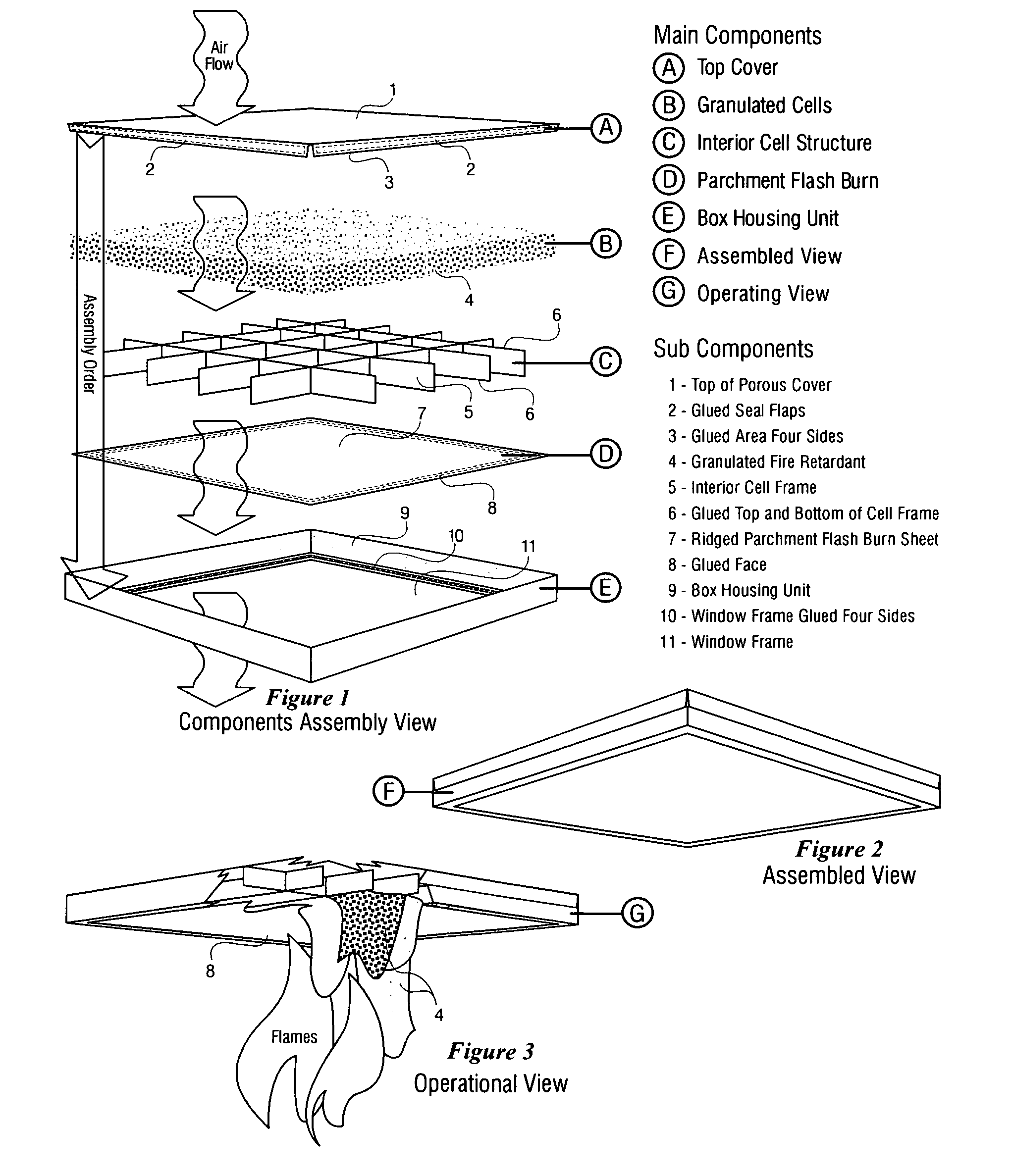
[0033]FIG. 1 illustrates in oblique view the five basic components of the invention within the assembly order of each components as they relate to a visual assembly and not necessarily a manufacturing assembly order. The Top Cover (1) consists of four sides with flaps (2) to be glued from the inside (3) of the flaps to the outside top surface of the box housing frame (9). The granulated fire retardant (4) which will be found made of natural substances or synthetic substances not limi...


PUM


Abstract

The Ceiling Firefighter is a Ceiling System (FIG. 2, Assembled View) designed for use within the ceilings of commercial, public and residential buildings that provides a method of mechanical fire extinguishing that offers an alternative or side by side enhancement to help overcome the nine before mentioned limitations of existing sprinkler systems. Comprised of five basic components of structure:(a) A flame resistant housing or box frame (9) whose face is set an opening or window (11), that conforms to standard ceiling system dimensions (FIG. 2, Assembled View).(b) A flash burn ridged parchment blister (7) which seals the window side of the box frame housing—secured in place with glue (8), to which its properties are measured to have a low kindling thermal range.(c) Internal glued (6) structural grid (5) whose main purpose is to reenforce both the ridged parchment flash burn blister (7) and to add overall strength to the unit itself. Secondary purpose is to minimize and limit damage to the unit's ridge parchment flash burn blister (7) to particular cells of the grid (5).(d) Granulated fire retardant packed within the housing box (4).(e) Top cover (1) with side flaps (2) on all four sides to be glued (3) to the outer top, outside surface main box housing (9).

Description

CROSS REFERENCE TO RELATED APPLICATIONS[0001]This application claims the benefit of Provisional Patent Application No. 61 / 272,800, Filing Date of Nov. 4, 2009.FEDERALLY SPONSORED RESEARCH[0002]Not ApplicableSEQUENCE LISTING OR PROGRAM[0003]Not ApplicableBACKGROUND [0004]1. Field[0005]As a mechanical device for extinguishing or containing the limitations of fire damage, its application relates to any building's ceiling tile systems that is packed with a flame retardant (4) used to extinguish fires as well as taking advantage of lost air filtration (1) from climate control systems within buildings. See FIGS. 1, 2, and 3.[0006]2. Prior Art[0007]In many commercial, public, and residential buildings, the primary fire extinguishing systems are individual extinguishing canisters and attic mounted sprinkler systems. Canister extinguishing systems require a hand held function thus operating these extinguishes in close proximity of the flames of a fire, putting the operator in danger of expos...

Claims


Application Information

Patent Timeline
IPC IPC(8): A62C3/00
CPCA62C99/0045A62C3/00
Inventor DICKENS, SR., JAMES DANIELDICKENS, JR., JAMES DANIEL
Owner DICKENS SR JAMES DANIEL
Learn More