Apparatus and method for signal quality measurement on gfsk signals

a signal quality and signal technology, applied in the field of digital communication systems, can solve the problem that the modulation scheme like gfsk is difficult to calculate evm-like measurements, and achieve the effect of accurately estimating the modulation index

Active Publication Date: 2011-04-21
MICROCHIP TECH INC
View PDF8 Cites 11 Cited by
  • Summary
  • Abstract
  • Description
  • Claims
  • Application Information

AI Technical Summary

Benefits of technology

[0007]Signal quality measurement like EVM in the Rx is quite popular for wireless communication systems. This signal quality measured may be used for many applications including product line testing and transmit power / rate control. However, EVM-like measurement is hard to calculate for some modulation schemes like GFSK. EVM-like measurement is even harder for Bluetooth GFSK signals because the modulation index is unknown to the Rx. The primary objective of the present invention is to provide a method for signal quality measurement on GFSK signals, which measures the received signal quality for a GFSK signal. To measure the signal quality of a GFSK signal with a varying modulation index, decoded bits and a simple 3-bit trellis of the frequency discriminator output are utilized. The trellis is pre-calibrated with a reference Rx. The modulation index can also be accurately estimated with this invention. Furthermore, the other primary objective of the present invention is to provide an apparatus for signal quality measurement on GFSK signals.
[0010]According to one aspect of the present invention, the signal quality measurement comprises: a frequency deviation information; a plurality of decoded bits; a plurality of averaging over samples units and a subtraction and division unit. The frequency deviation information is used for measuring a receive power and a noise power. The plurality of decoded bits is used for measuring the noise power on the current frequency deviation information by comparing with a plurality of pre-calibrated trellis. The plurality of averaging over samples units is used for making the receive power and the noise power become accurate and reliable. The subtraction and division unit is used for calculating a ratio of the receive power and the noise power as a quality indicator to obtain a signal quality.

Problems solved by technology

However, EVM-like measurement is hard to calculate for some modulation schemes like GFSK.

Method used


Image

  • Apparatus and method for signal quality measurement on gfsk signals
  • Apparatus and method for signal quality measurement on gfsk signals
  • Apparatus and method for signal quality measurement on gfsk signals

Examples


Embodiment Construction

[0018]Although the invention has been explained in relation to several preferred embodiments, the accompanying drawings and the following detailed descriptions are the preferred embodiment of the present invention. It is to be understood that the following disclosed descriptions will be examples of present invention, and will not limit the present invention into the drawings and the special embodiment.

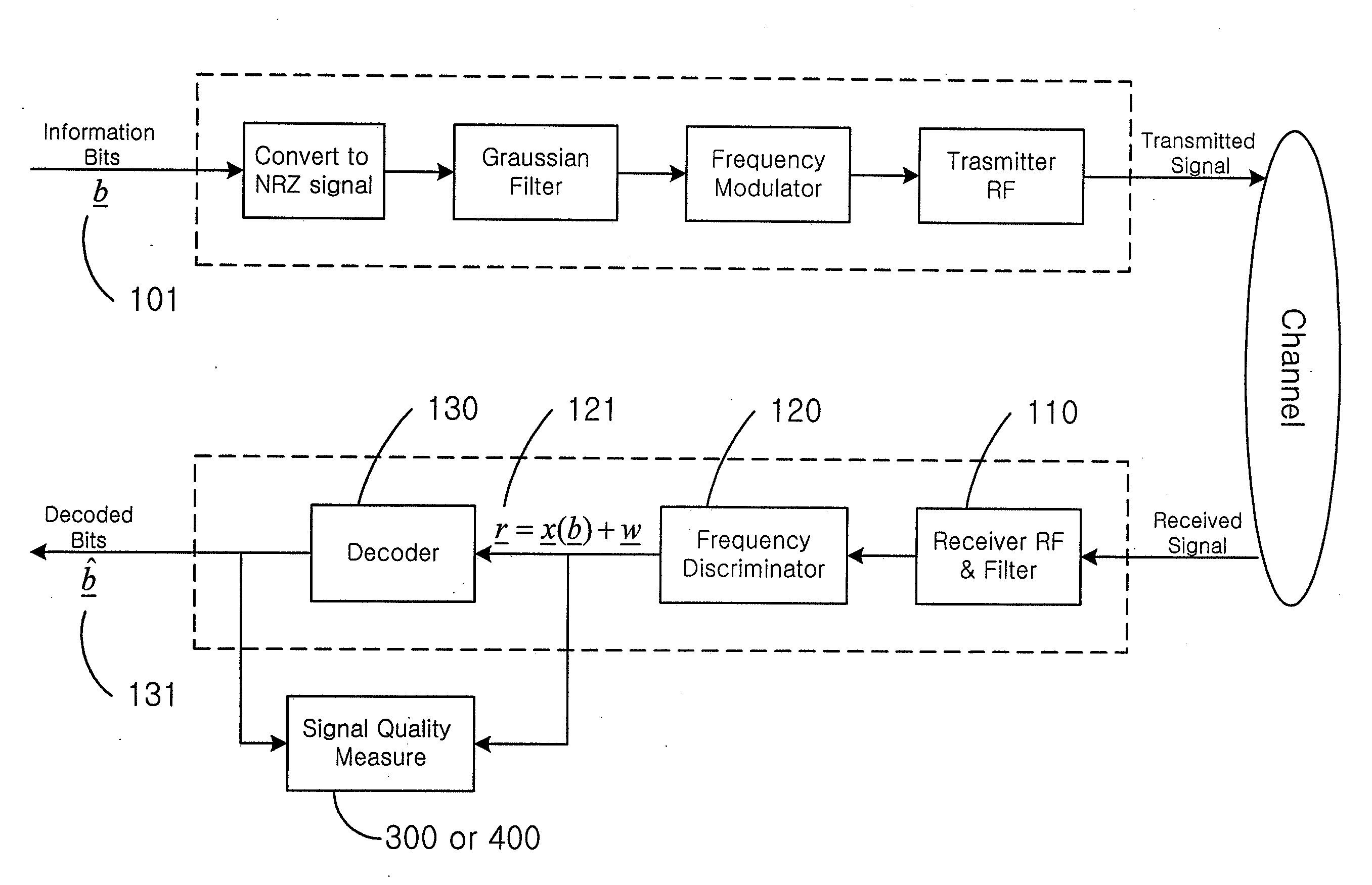
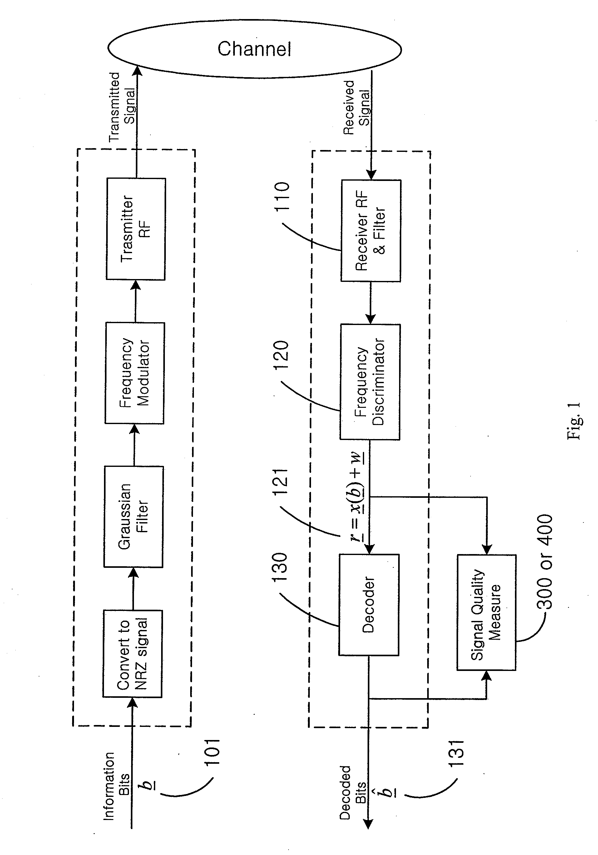
[0019]Bluetooth is a wireless protocol for personal area networks. In the radio specification of the Bluetooth standard, the Basic Data Rate (BDR) uses GFSK as modulation type. The bandwidth period product used is 0.5 (BT=0.5), and the modulation index h shall be between 0.28 and 0.35. For a GFSK modulation, one symbol represents one bit, and a binary one shall be represented by a GFSK waveform with positive frequency deviation. And a binary 0 is represented by a GFSK waveform with negative frequency deviation.

[0020]Referring to FIG. 1, it shows a diagram for a typical GFSK Tx and a co...


PUM


Abstract

The present invention discloses an effective apparatus and method to measure the received signal quality for a GFSK modulated signal with (or without) an unknown modulation index. The signal quality measurements are based on the decoded (unknown or known) bits and the trellis of the frequency discriminator output. This trellis is pre-calibrated with a reference Rx. The transmitted modulation index is also accurately estimated in this invention.

Description

BACKGROUND OF THE INVENTION[0001]1. Field of the Invention[0002]The present invention generally relates to digital communication systems, and more particularly to methods for signal quality measurements on Gaussian frequency shift keying (GFSK) signals.[0003]2. Description of the Related Art[0004]For communication systems, received signal quality measurements are important for several reasons. One of the reasons is the production line testing (PLT). PLT is required to determine whether every component in a transmitter (Tx) and a receiver (Rx) works correctly. In order for PLT to be passed and product shipped, all the measured signal qualities must meet the product specifications. Another reason is that this measured signal quality may be used for an indicator of the current physical channel condition including the Tx and the Rx distortions. This signal quality measured may be widely utilized. For example, by measuring the signal quality, the supported data rates for a current wirele...

Claims


Application Information

Patent Timeline
IPC IPC(8): H04B17/00H04L27/14
CPCH04L25/06H04B17/336H04L27/22H04L27/2017
Inventor KIM, PANSOPCHEN, JENG-HONGLIU, HSIN-HSIANG
Owner MICROCHIP TECH INC
Why Eureka
Try Eureka