
Image sensing system and correction method

a technology of image sensing and correction method, applied in the direction of picture signal generators, color signal processing circuits, solid-state device signal generators, etc., can solve the problems of excessive or poor correction, and achieve the effect of accurately detecting the luminance of an object and improving the accuracy of color shading correction

Inactive Publication Date: 2011-04-21
CANON KK
View PDF7 Cites 9 Cited by
  • Summary
  • Abstract
  • Description
  • Claims
  • Application Information

AI Technical Summary

Benefits of technology

[0008]The present invention provides a technique advantageous to improve the accuracy of color shading correction by accurately detecting the luminance of an object in a wavelength range in the vicinity of the cutoff wavelength relative to the average luminance of the object.

Problems solved by technology

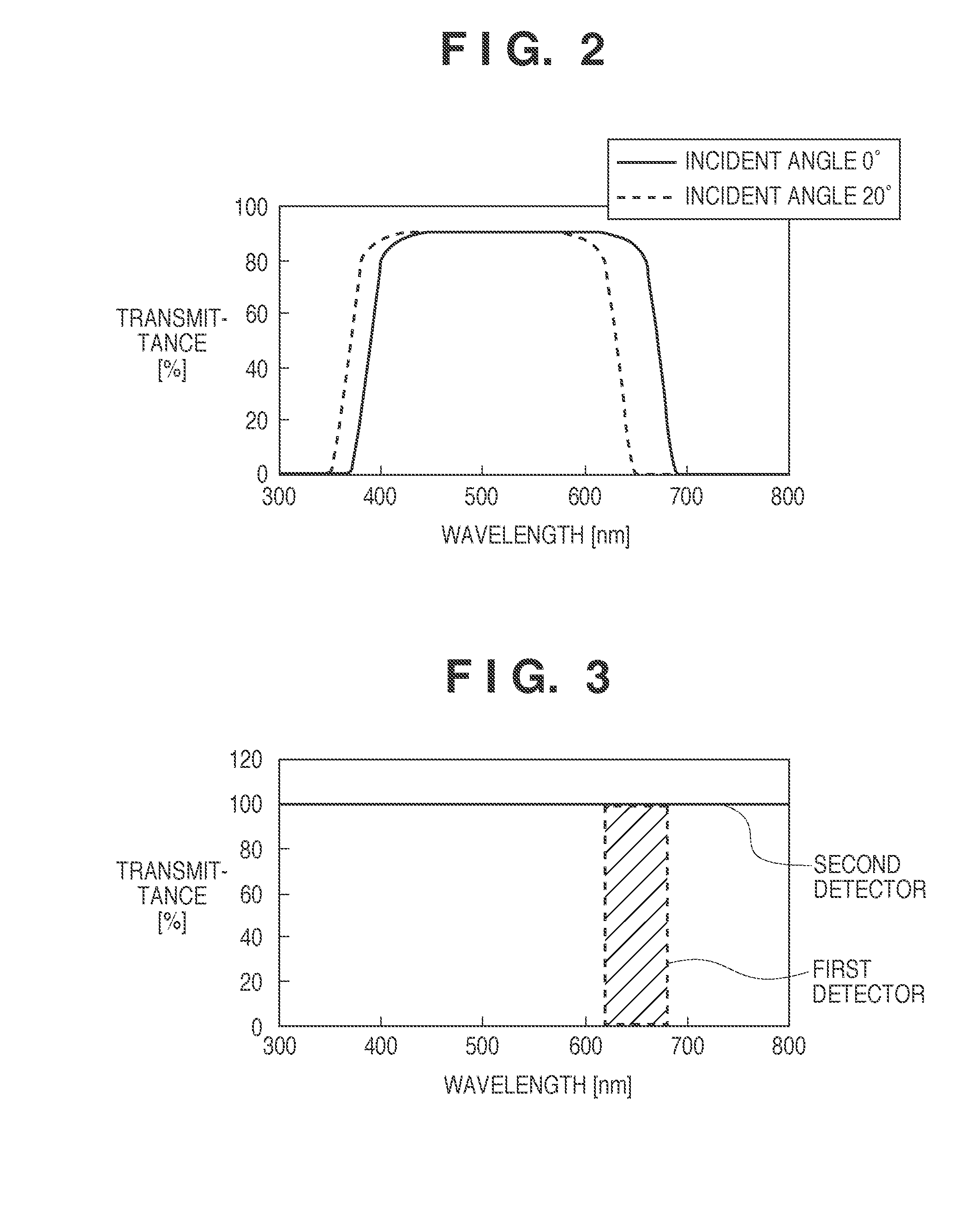
Therefore, the luminance of an object in a wavelength range in the vicinity of the cutoff wavelength relative to the average luminance of the object cannot be detected with high accuracy, and this may lead to excessive or poor correction.

Method used


Image

  • Image sensing system and correction method
  • Image sensing system and correction method
  • Image sensing system and correction method

Examples


Embodiment Construction

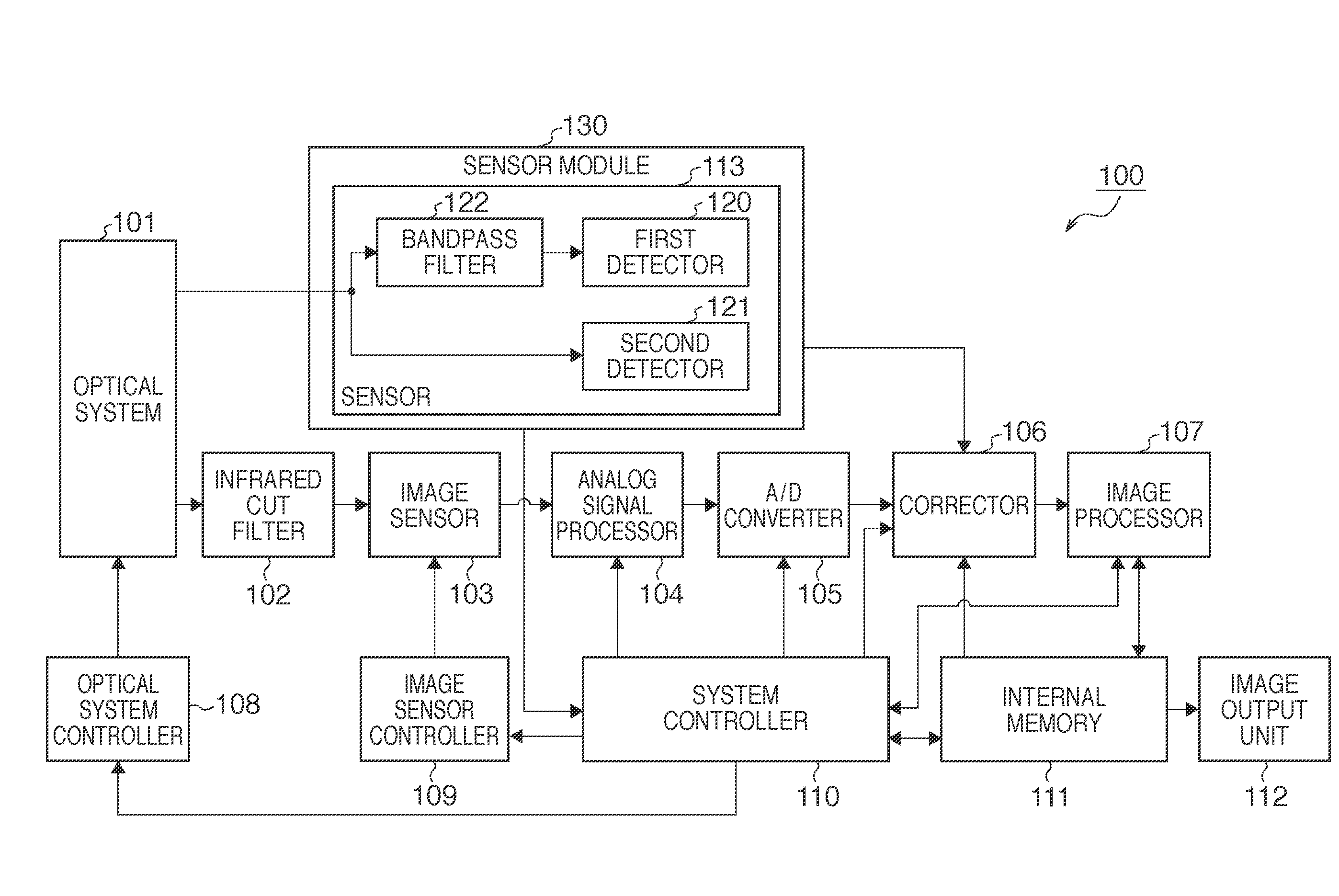
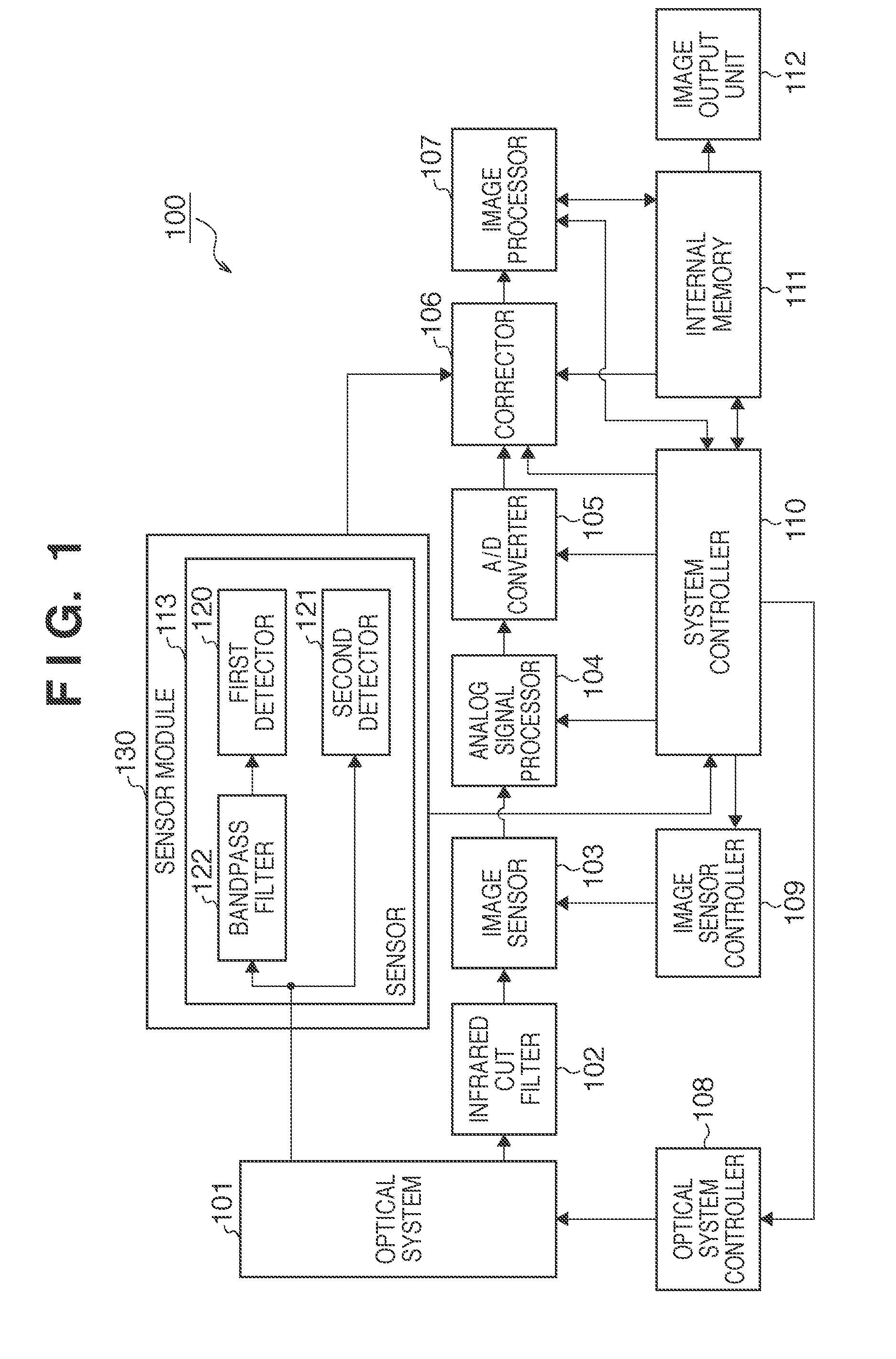
[0019]An image sensing system according to the present invention is applicable to digital cameras such as a digital single-lens reflex camera, a digital compact camera, and a digital movie camera. In the image sensing system according to the present invention, an optical system which forms an image of an object on the image sensing surface of an image sensor may be exchangeable or fixed.

[0020]The configuration and operation of a digital single-lens reflex camera (to be simply referred to as a camera hereinafter) 100 as one embodiment of an image sensing system according to the present invention will be described with reference to FIG. 1. The camera 100 includes an image sensor 103 having an image sensing surface, and an infrared cut filter 102 arranged between the image sensing surface and an optical system 101 which forms an image of an object on the image sensing surface. The camera 100 also includes a sensor 113 and corrector 106. The sensor 113 detects the luminance of an object...


PUM


Abstract

An image sensing system comprises an image sensor having an image sensing surface, a filter arranged between the image sensing surface and an optical system which forms an image of an object on the image sensing surface, a sensor configured to detect a luminance of the object in a band in the vicinity of a cutoff wavelength of the filter relative to an average luminance of the object via the optical system, and a corrector configured to execute color shading correction of the image, sensed by the image sensor, using a color shading correction coefficient determined by the relative luminance detected by the sensor.

Description

BACKGROUND OF THE INVENTION[0001]1. Field of the Invention[0002]The present invention relates to an image sensing system and a correction method.[0003]2. Description of the Related Art[0004]Image sensors typified by a CCD image sensor and a CMOS image sensor have higher sensitivities to infrared light than the spectral sensitivity characteristic (spectral luminous efficiency) of human eyes. Hence, an infrared cut filter can generally be arranged between a camera lens and the image sensing surface of an image sensor. A dichroic filter, for example, can be used as the infrared cut filter.[0005]A principal ray which reaches the center of the dichroic filter upon passing through the camera lens is perpendicular to the dichroic filter surface, whereas that which reaches the periphery in the plane of the image sensing surface of the image sensor makes a certain angle with the dichroic filter surface. The larger the distance from the center of the image sensing surface (i.e., the higher th...

Claims


Application Information

Patent Timeline
IPC IPC(8): H04N9/64
CPCH04N9/646H04N9/045H04N23/843
Inventor KOIZUMI, SATOSHI
Owner CANON KK
Learn More