
Airplane configuration

a technology for aircraft and configuration, applied in the field of aircraft design, can solve the problems of excessive noise, heat, and undesirable noise, and achieve the effect of reducing the noise level

Inactive Publication Date: 2011-04-21
THE BOEING CO
View PDF3 Cites 12 Cited by
  • Summary
  • Abstract
  • Description
  • Claims
  • Application Information

AI Technical Summary

Benefits of technology

This configuration significantly reduces noise and infrared radiation directed towards the ground, enhancing community safety and reducing the aircraft's visibility to potential threats, while maintaining desired flight characteristics and performance.

Problems solved by technology

Excessive sound is undesirable largely because of disturbance to surrounding communities.
Heat is undesirable particularly in both military and civil aircraft, which may be tracked by ground-based missiles that seek heat in the form of infrared radiation.
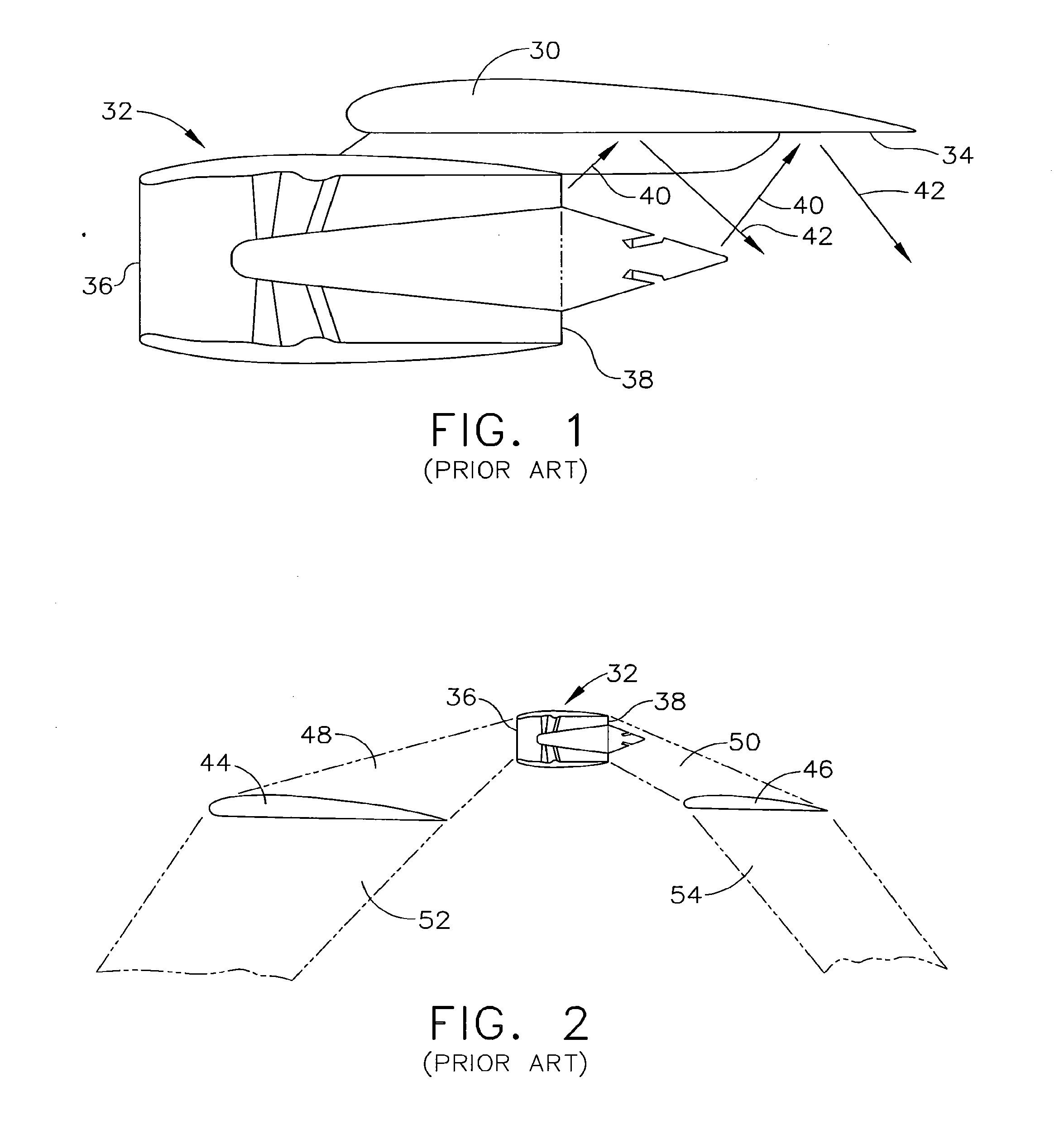
Both the under-surface reflection and the engine plume interaction with the wing trailing edge add to the overall noise heard below.
This issue is exacerbated by the conventional under-wing mount, because radiant heat energy also reflects off the pylon and underside of the wing, much like noise energy.
Regional air transportation poses community environment intrusion as operations are confined within lower speed regimes that result in longer exposure times, at lower altitude ceilings, and over a much larger swath of communities than ever before.
In these military configurations, the regional jet flight regimes and likelihood of operating in increasing hostile threat environments will likely expose the aircraft, at some point, to vehicle-transported and man-portable infrared (IR) air defense systems, which can track and guide on the heat radiated by the aircraft.
Another emergent issue associated with increased traffic frequency is the noise produced by thrust-reversing systems.
The issue is compounded both by increased traffic and how thrust reversing systems are employed in maximizing operational efficiency.
Thrust reversing events are typically low frequency in nature, can be heard up to a mile from the airport, and have been demonstrated to cause structure rattle in buildings close to the airport.

Method used


Image

  • Airplane configuration
  • Airplane configuration
  • Airplane configuration

Examples


Embodiment Construction

[0038]The following detailed description of preferred embodiments refers to the accompanying drawings that illustrate specific embodiments of the invention. Other embodiments having different structures and operations do not depart from the scope of the present invention.

[0039]In the Figures herein, unique features receive unique reference numerals, while features that are the same in more than one drawing receive the same reference numerals throughout. The scope of the invention is not intended to be limited by materials, but may be carried out using any materials that allow the construction and operation of the present invention. Materials and dimensions depend on the particular application. The embodiments of the present invention may be used for any aircraft, whether private, commercial, or military, of any size.

[0040]Jet engines are shrouded turbofans. With escalation in fuel prices, interest in highly efficient next-generation turbo-prop (or turbo-shaft) and prop-fan propulsio...


PUM


Abstract

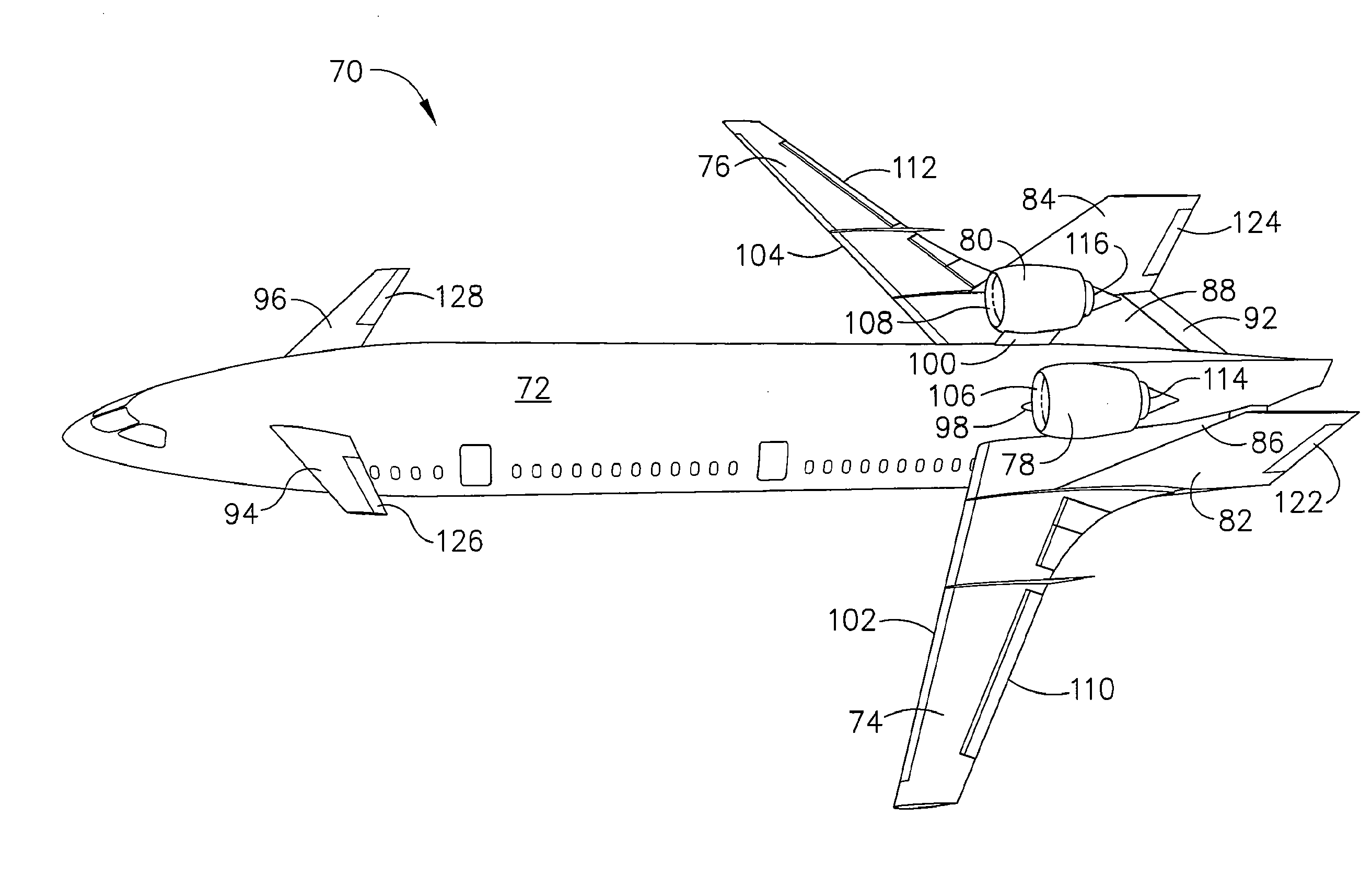
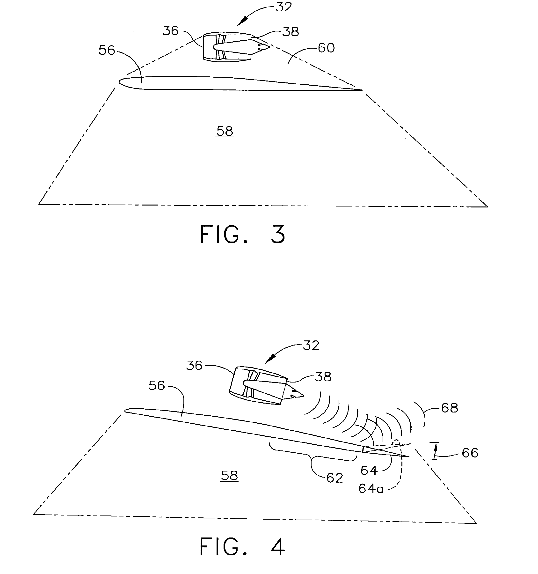
An aircraft configuration that may reduce the level of noise, infrared radiation, or combination thereof directed towards the ground from an aircraft in flight. An embodiment of an aircraft includes a fuselage, two forward swept wings, at least one engine mounted to the aircraft and higher than the wings, and vertical stabilizers mounted on each wing outboard of the outermost engine. The leading edge of the wing may extend forward of the leading end of the engine, and the trailing edge of the aft deck may extend aft of the trailing end of the engine. The aft deck may include an upwardly rotatable pitch control surface at the trailing edge of the deck. Engine types may vary, including but not limited to turbofans, prop-fans, and turbo-props. Main wings may be mounted above the longitudinal axis of the fuselage, and canards may likewise be mounted above or below the axis.

Description

CROSS-REFERENCE TO RELATED APPLICATION[0001]This application is a divisional of co-pending patent application Ser. No. 11 / 612,594, filed Dec. 19, 2006 and titled “Airplane Configuration,” the entire disclosure of which is hereby incorporated by reference.BACKGROUND OF THE INVENTION[0002]This invention relates to the field of aircraft design, and more particularly to an airplane configuration in which an engine is wholly above a wing, aft deck, or combination thereof and at least in part between vertical stabilizers.[0003]Aircraft engines generate sound and heat in their operation. Excessive sound is undesirable largely because of disturbance to surrounding communities. Heat is undesirable particularly in both military and civil aircraft, which may be tracked by ground-based missiles that seek heat in the form of infrared radiation. The design of the aircraft profoundly impacts the sound and heat that are observed from the ground.[0004]Conventional subsonic civil aircraft designs com...

Claims


Application Information

Patent Timeline
Patent Type & Authority Applications(United States)
IPC IPC(8): B64C1/40B64C1/00
CPCB64C39/12Y10T29/49826B64D27/20B64D27/14
Inventor MOORE, MATTHEW D.BOREN, KELLY L.MARQUES, EDWARD C.
Owner THE BOEING CO
Learn More