
Exhaust Component

Inactive Publication Date: 2011-03-31
STANLEY RONALD LEE
View PDF11 Cites 4 Cited by
  • Summary
  • Abstract
  • Description
  • Claims
  • Application Information

AI Technical Summary

Benefits of technology

[0010]The present inventor realized in an inventive moment that if, at the point of expansion, exhaust gases could be caused to diverge in path and muffled while traveling separate paths and then be harmonically collected for a stereo output, better resonance and pulse definition in the overall exhaust sound might result. The inventor therefore constructed a unique type of exhaust component arrangement for exhaust systems that allowed gases to expand and flow unrestricted through two or more sound deadening devices and to be collected and merged at output from the exhaust system with minimal pulse wave collision or bouncing inside the exhaust pipe or exhaust components. A significant improvement in sound quality and definition of the exhaust pulses emanating from the exhaust pipes results with no impediment to gas expansion or gas flow created.
[0016]According to another aspect of the present invention, using an exhaust component, the component including an inlet portion, two or more separator components fixed to the inlet portion so as to present a separation interface at the point in the exhaust component where they are fixed to the inlet portion, two or more chambers fixed to the separator components, two or more collector components fixed to the chambers opposite the separator components, one or more outlet portions fixed to the collector components at the end opposite the chambers, a method for improving sound quality of an exhaust system is provided and includes the steps (a) activating an exhaust system to produce an exhaust stream, (b) separating the exhaust stream into two or more streams, (c) muffling the sound of the streams, (d) collecting the separate streams after muffling, and (e) merging the streams at outlet of the exhaust component.

Problems solved by technology

A problem stated above is that better sounding exhaust systems are desirable for any personal truck or automobile, but many of the conventional means for muffling or attenuating the sound of an exhaust system such as mufflers and resonators, also create higher noise ratios and lower definition rates between sound pulses emanating from the exhaust system.

Method used


Image

  • Exhaust Component
  • Exhaust Component
  • Exhaust Component

Examples


Embodiment Construction

[0026]The inventors provide a system and methods for attenuating and shaping compression pulse sound waves characteristic of exhaust gasses traveling through a vehicle exhaust system that provides signal attenuation and modification with minimal reflection to enhance pulse definition and sound quality at the point of exit of the exhaust for the exhaust component or components. The present invention is described in enabling detail according to the presented examples, which may represent more than one embodiment of the present invention.

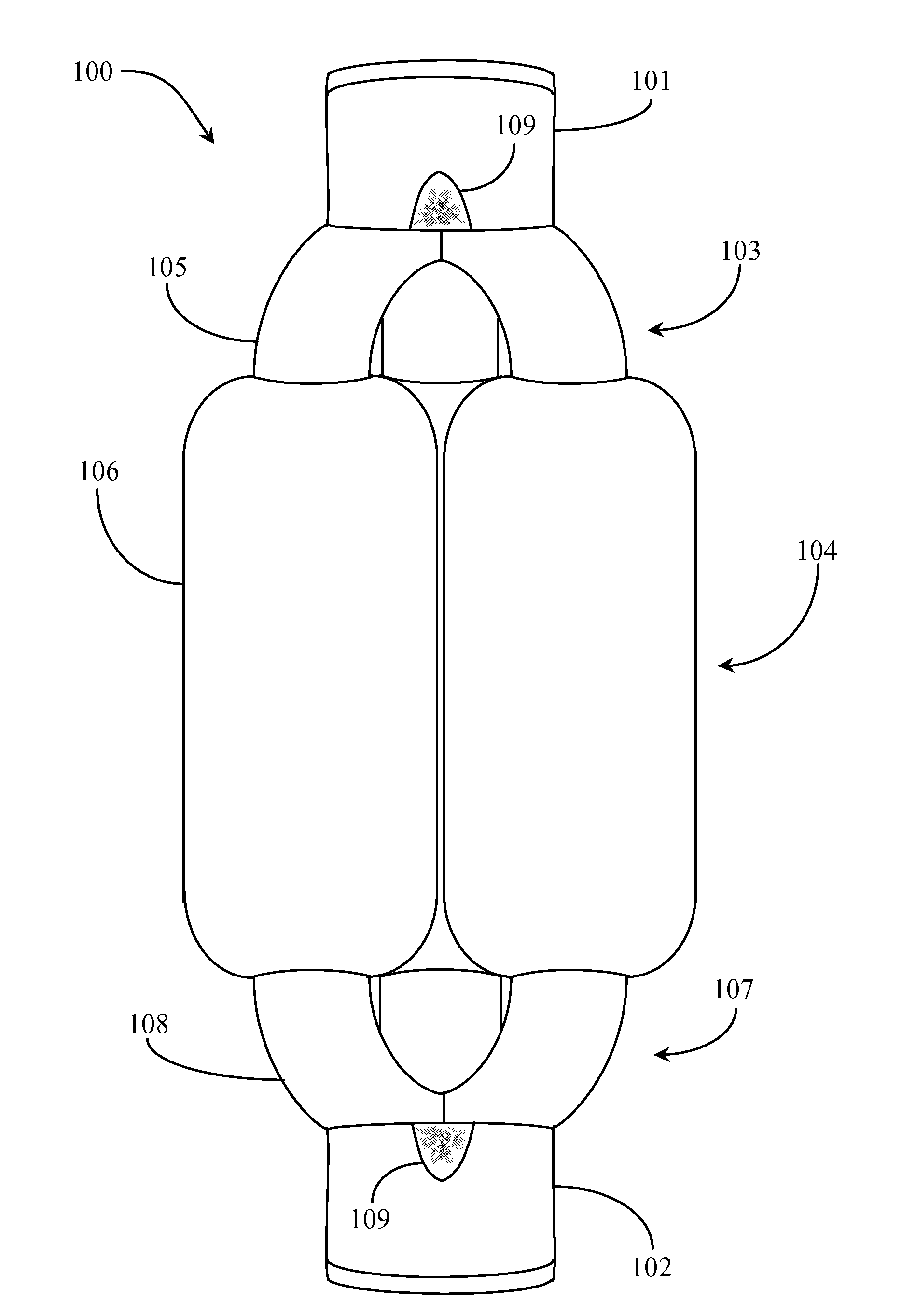
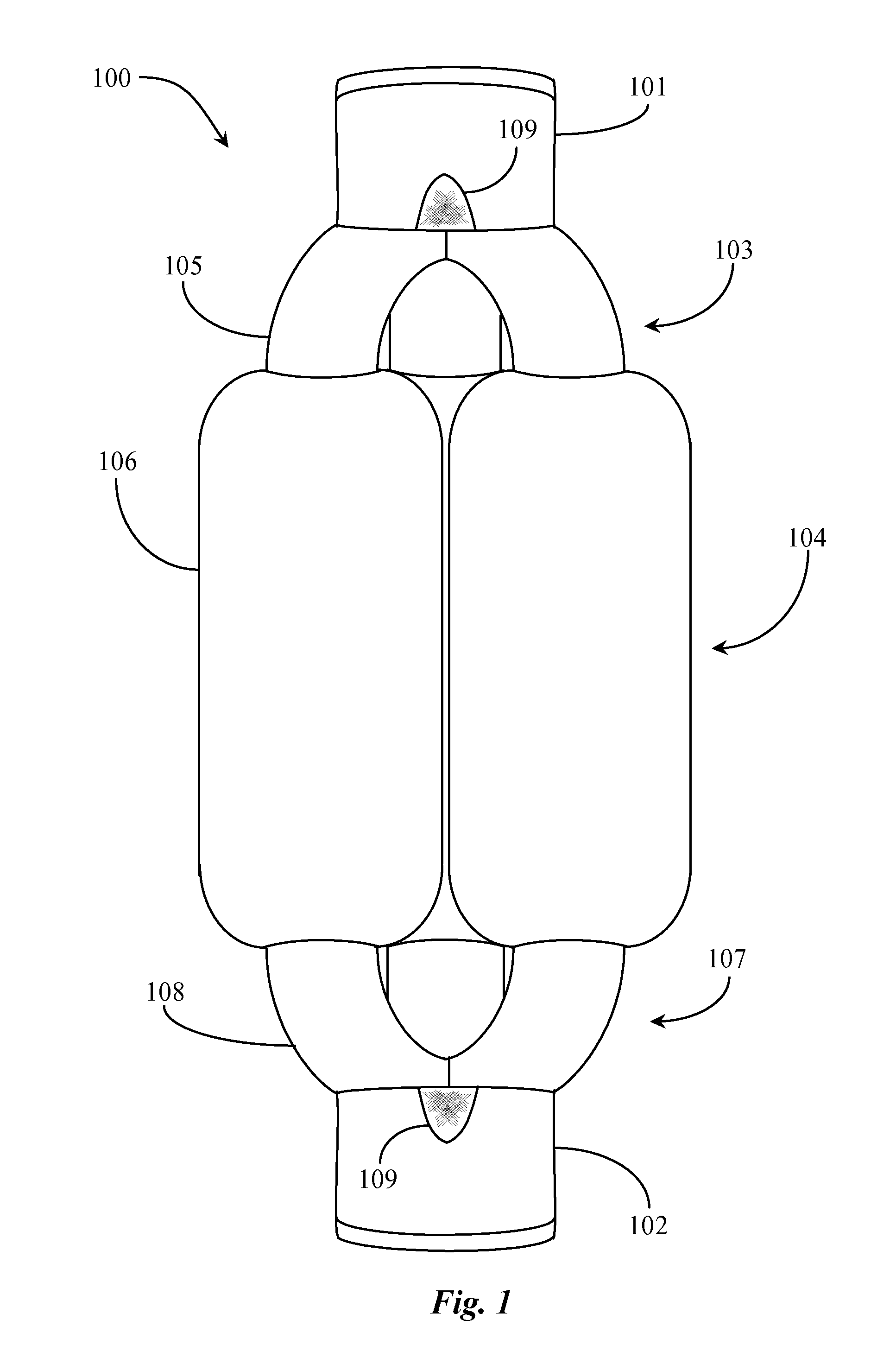
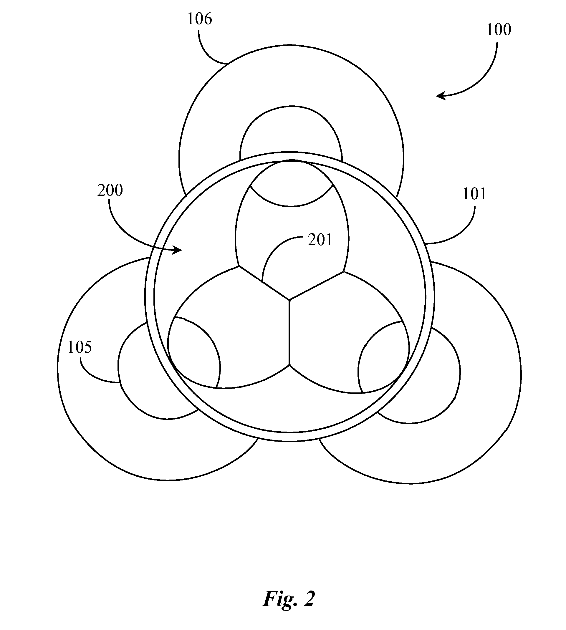
[0027]FIG. 1 is a plan view of an exhaust component 100 according to an embodiment of the present invention. Referring now to FIG. 1, an exhaust component 100 referred to herein as a wave pulse attenuation device is illustrated in plan view. Device 100 is manufactured of a stainless steel or another suitable metal or composite for use in exhaust systems of both diesel and gas combustion engines. Device 100 is adapted to replace a stock muffler on an ex...


PUM


Abstract

An exhaust component is provided including an inlet portion for accepting an exhaust stream entering therein from an exhaust system, two or more separator components fixed to the inlet portion for separating the exhaust stream into two or more streams at the point of egress from the inlet portion, two or more chambers fixed to the separator components, the chambers for muffling sound of the exhaust stream, two or more collector components fixed to the chambers opposite the separator components for collecting the separated exhaust streams upon egress from the chambers, and one or more outlet portions fixed to the collector components at the end opposite the chambers for carrying separated or merged exhaust streams out of the exhaust component.

Description

CROSS-REFERENCE TO RELATED DOCUMENTS[0001]The present application claims priority to provisional applications Ser. No. 61 / 246,429, filed Sep. 28, 2009, and 61 / 250,233, filed Oct. 9, 2009, the entire disclosures of the provisional applications are incorporated herein at least by reference.BACKGROUND OF THE INVENTION[0002]1. Field of the Invention[0003]The present invention is in the field of vehicle exhaust systems and components and pertains particularly to methods and apparatus for processing exhaust gasses in an exhaust system to mitigate noise and improve sound quality.[0004]2. Discussion of the State of the Art[0005]In the field of exhaust systems products for vehicles, mufflers and stock resonators are available on the market for muffling and dampening noise from vehicle exhaust. A variety of different muffler or resonator products have been provided with a focus on cleaning up noise in the exhaust system and improving resonance and definition of the exhaust pulses, as they exi...

Claims


Application Information

Patent Timeline
IPC IPC(8): F01N1/08
CPCF01N1/003F01N1/006F01N1/24F01N2490/18F01N13/08F01N2310/02F01N2470/00F01N13/04
Inventor STANLEY, RONALD LEE
Owner STANLEY RONALD LEE
Learn More