Wafer level integration module with interconnects

a technology of interconnection and integrated circuit, which is applied in the direction of electrical testing, instruments, electrical apparatus, etc., can solve the problems of cumbersome handling of wafers, time-consuming and time-consuming cutting notches, and limited i/o density of ic devices that are fabricated by conventional processes

Inactive Publication Date: 2011-03-17
VISWANADAM GAUTHAM
View PDF6 Cites 2 Cited by
  • Summary
  • Abstract
  • Description
  • Claims
  • Application Information

AI Technical Summary

Benefits of technology

[0009]In an embodiment the depressions form microstructures. The conductive layer is a high temperature conductive film. The conductive interconnect film may be exposed by chemical mechanical polishing. A substrate may be

Problems solved by technology

weight. However, the resulting IC device that is fabricated by the conventional processes is limited by I / O density as the chip size determines the package I / O
The step of cutting notches is sequential and therefore is time-consuming, and also requires an accurate fixed angular shaped cutting blade for cutting the notches.
A cut wafer is then transported into the clean room for further processing, making handling of the wafer cumbersome.
Additionally, the two protective layers on a resultant die also increase the cost of fabrication.
The conventional fabricating methods disclose packaging / interconnection of the device IOs to the external system after the devices are pre-fabricated, which limits the number of IOs and functionality of device per square of silicon area.
Risk involved in loosing wafer yields is highly dependent on the amount of handling and process stages the device wafer undergoes after the wafer reaches packaging and assembly houses.
Such conventional fabrication methods typically require additional device packaging methods after the devices are fabricated at the semiconductor wafer fabrication facilities which results in exposing the processed device to increased risk of contamination and damage.

Method used


Image

  • Wafer level integration module with interconnects
  • Wafer level integration module with interconnects
  • Wafer level integration module with interconnects

Examples


Embodiment Construction

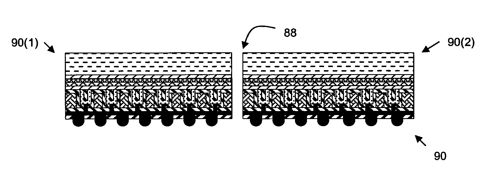
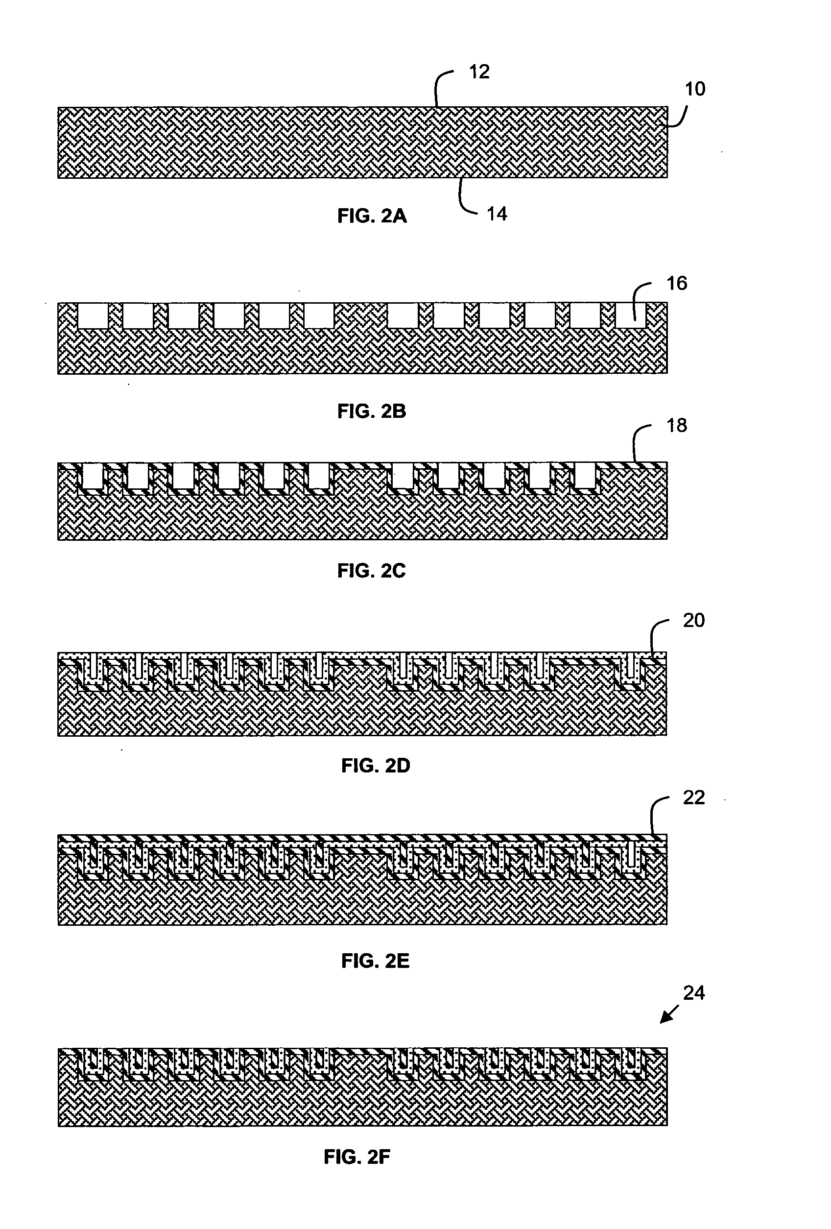
[0020]According to an embodiment of the present invention, there is provided a method 200 of manufacturing an integrated circuit (IC) device 90. According to the method, a wafer 10 is first provided having a first or top surface and a second or bottom surface. The wafer may be a blank polished or unpolished silicon wafer or the like. High aspect ratio micro-structures 16 that are specifically designed to provide a die level interconnect configuration and mapping, are provided on the first blank surface 12 of the wafer. The wafer with pre-formed conductive interconnect microstructures 16 are further processed for device fabrication, for example, at the wafer fabrication facilities. Once the front side 12 devices are fabricated, the silicon material 20 is then removed from a second side 14 of the device wafer 10, opposite the first side, to expose the high temperature conductive interconnect microstructures 16. Contacts are formed on the second side of the device wafer using conductiv...


PUM


Abstract

A method and apparatus for manufacturing an integrated circuit (IC) device (90) is disclosed. A wafer (10) is first provided having a first or top surface and a second or bottom surface. The wafer may be a blank polished or unpolished silicon wafer or the like. High aspect ratio micro-structures (16) that are specifically designed to provide a die level interconnect configuration and mapping, are provided on the first blank surface (12) of the wafer. The wafer with preformed conductive interconnect microstructures (16) are further processed for device fabrication, for example, at the wafer fabrication facilities. Once the front side (12) devices are fabricated, the silicon material (20) is then removed from a second side (14) of the device wafer (10), opposite the first side, to expose the high temperature conductive interconnect microstructures (16). Contacts are formed on the second side of the device wafer using conductive metal. These contacts are electrically connected to the interior of the microstructures and thereby electrically connect with the functional device (26). The dies (90(1)),(90(2)) are separated along the separation zones (88) between the dies to produce individualized functional and packaged dies, each of which serves as a fully packaged IC device (90).

Description

FIELD OF THE INVENTION[0001]This invention relates generally to an integrated circuit (IC) device and a method of manufacturing an IC device. More particularly, this invention relates to an IC device including one or more dies arranged in an array configuration within the defined wafer geometry, and to a method of manufacturing such an IC device.BACKGROUND OF THE INVENTION[0002]With the miniaturization of electronic products, there is a continuous need to reduce the size of devices and to add more functionality so that more IC devices can be accommodated area on a substrate. In prior IC device fabrication, an IC device has a foot print approximately the size of a die of the IC device. Multiple dies with multiple interconnection pads on each die are processed together to form a semiconductor wafer first. The devices that have been arrayed on the wafer are then packaged in many ways. Two such conventional packaging methods include separating the dies from the arrayed wafer prior to pa...

Claims


Application Information

Patent Timeline
IPC IPC(8): H01L21/66H01L21/50
CPCH01L21/76898H01L22/14H01L2924/1461H01L2224/131H01L2224/02372H01L2924/10329H01L2924/01076H01L22/20H01L22/32H01L24/03H01L24/11H01L24/13H01L24/94H01L29/735H01L2224/0401H01L2224/94H01L2924/01013H01L2924/01014H01L2924/01029H01L2924/01032H01L2924/01033H01L2924/01049H01L2924/01057H01L2924/01079H01L2924/01082H01L2924/014H01L2924/09701H01L2924/14H01L2924/1433H01L2924/19041H01L2924/19042H01L2924/19043H01L2924/01005H01L2924/01006H01L2224/11H01L2924/00
Inventor VISWANADAM, GAUTHAM
Owner VISWANADAM GAUTHAM
Why Eureka
Try Eureka