Reduced angular emission cone illumination leds

Inactive Publication Date: 2011-03-17
KONINKLIJKE PHILIPS ELECTRONICS NV +1
View PDF5 Cites 50 Cited by
  • Summary
  • Abstract
  • Description
  • Claims
  • Application Information

AI Technical Summary

Benefits of technology

[0004]In one or more embodiments of the present disclosure, a light emitting diode (LED) package includes an integrated package level reflector formed around an LED die. The reflector reduces the light emission angle of the LED package so the LED package may be used as a light source in overhead light fixtures.

Problems solved by technology

These diffusers may impact the aesthetics of the lighting fixtures by increasing the thickness of the lighting fixtures.
LEDs typically generate Lambertian emissions that do not meet the glare regulations for overhead lighting.

Method used


Image

  • Reduced angular emission cone illumination leds
  • Reduced angular emission cone illumination leds
  • Reduced angular emission cone illumination leds

Examples


Embodiment Construction

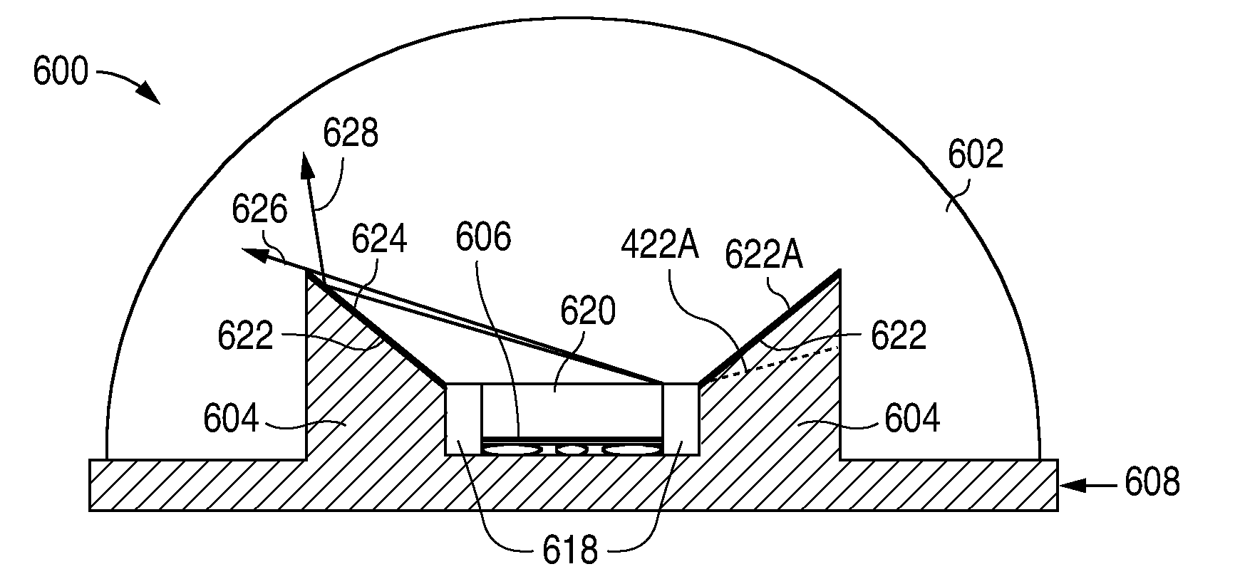
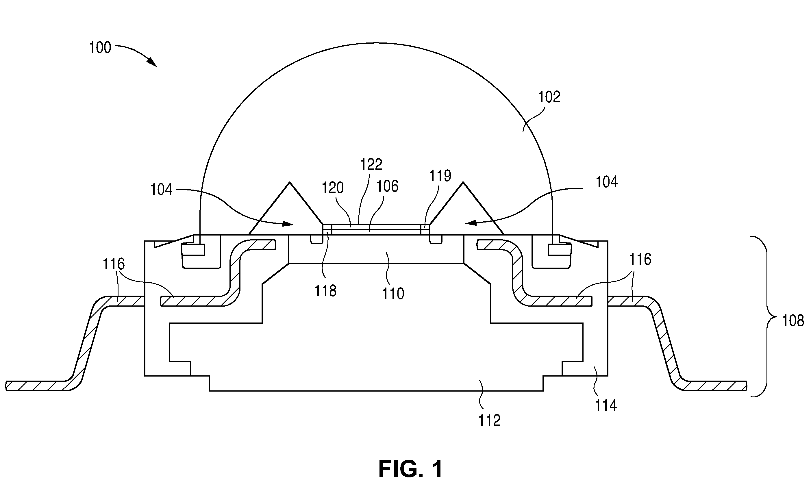
[0015]FIG. 1 illustrates a cross-sectional view of a light emitting diode (LED) package 100 with a lens 102 integrated with an integrated package level reflector 104 in one or more embodiments of the present disclosure. Lens 102 encapsulates an LED die 106 on a support 108. Support 108 may include a submount or interposer 110, a heat sink 112, and a leadframe or housing 114. LED die 106 is mounted on interposer 110. Interposer 110 has conductive traces that electrically couple LED die 106 to bond wire pads on the interposer. Interposer 110 is mounted on heat sink 112. Heat sink 112 dissipates heat from LED die 106. Heat sink 112 is received in housing 114. Bond wires (not shown) electrically couple the pads on interposer 110 to electrical leads 116 of housing 110, which pass electrical signals between LED package 100 and external components.

[0016]LED die 106 may include an n-type layer, a light-emitting layer (common referred to as the “active region”) over the n-type layer, a p-typ...


PUM


Abstract

A light emitting diode (LED) package includes a support, an LED die mounted on the support, a reflector around the LED die, and a lens over the LED die. The reflector has an angled reflective surface that limits the light emission angle from the LED package. The reflector is a part of the lens or the support.

Description

FIELD OF INVENTION[0001]The present disclosure relates to light emitting diode (LED) packages and, in particular, to LED packages that meets glare regulations for overhead lighting.DESCRIPTION OF RELATED ART[0002]Overhead lighting fixtures may have to meet glare regulations that limit brightness over certain emission angle (e.g., less than 1000 cd / m2 for angles greater than 65 degrees). Some lighting fixtures use diffusers to limit their emission angles. These diffusers may impact the aesthetics of the lighting fixtures by increasing the thickness of the lighting fixtures.[0003]More and more lighting fixtures are using light emitting diodes (LEDs) are their light source because LEDs are energy efficient and have a long life. LEDs typically generate Lambertian emissions that do not meet the glare regulations for overhead lighting. Thus, what are needed are LEDs that generate radiation patterns that meet glare regulations for overhead lighting.SUMMARY[0004]In one or more embodiments o...

Claims


Application Information

Patent Timeline
IPC IPC(8): H01L33/00H01L21/00
CPCH01L33/46H01L33/483H01L2224/48247H01L33/60H01L33/54
Inventor BIERHUIZEN, SERGE J.CRAFORD, M. GEORGE
Owner KONINKLIJKE PHILIPS ELECTRONICS NV
Why Eureka
Try Eureka