
Accelerated weathering technique

a weathering technique and accelerated technology, applied in the field of accelerated weathering techniques, can solve the problems of difficult water droplets to drain off the painted surface, photooxidation and degradation of automotive paint materials, and hydrolysis of paint materials and subsequently,

Inactive Publication Date: 2011-03-17
HONDA MOTOR CO LTD
View PDF35 Cites 19 Cited by
  • Summary
  • Abstract
  • Description
  • Claims
  • Application Information

AI Technical Summary

Benefits of technology

The present invention is an accelerated weathering device that can control the temperature, humidity, and spectral irradiation of a work piece. The device includes a weathering chamber, a means for supporting the work piece, a central controller unit, a work piece temperature control device, a humidity control unit, and a spectral irradiation unit. The technical effects of this invention include improved durability and reliability of the work piece, faster weathering times, and better control over the weathering process.

Problems solved by technology

Condensation that forms on automotive paint materials leads to hydrolysis of the paint material and subsequently photooxidation and degradation of the automotive paint material.
In this orientation, it is very difficult for water droplets to drain off of the painted surface.

Method used


Image

  • Accelerated weathering technique
  • Accelerated weathering technique
  • Accelerated weathering technique

Examples


embodiment 100

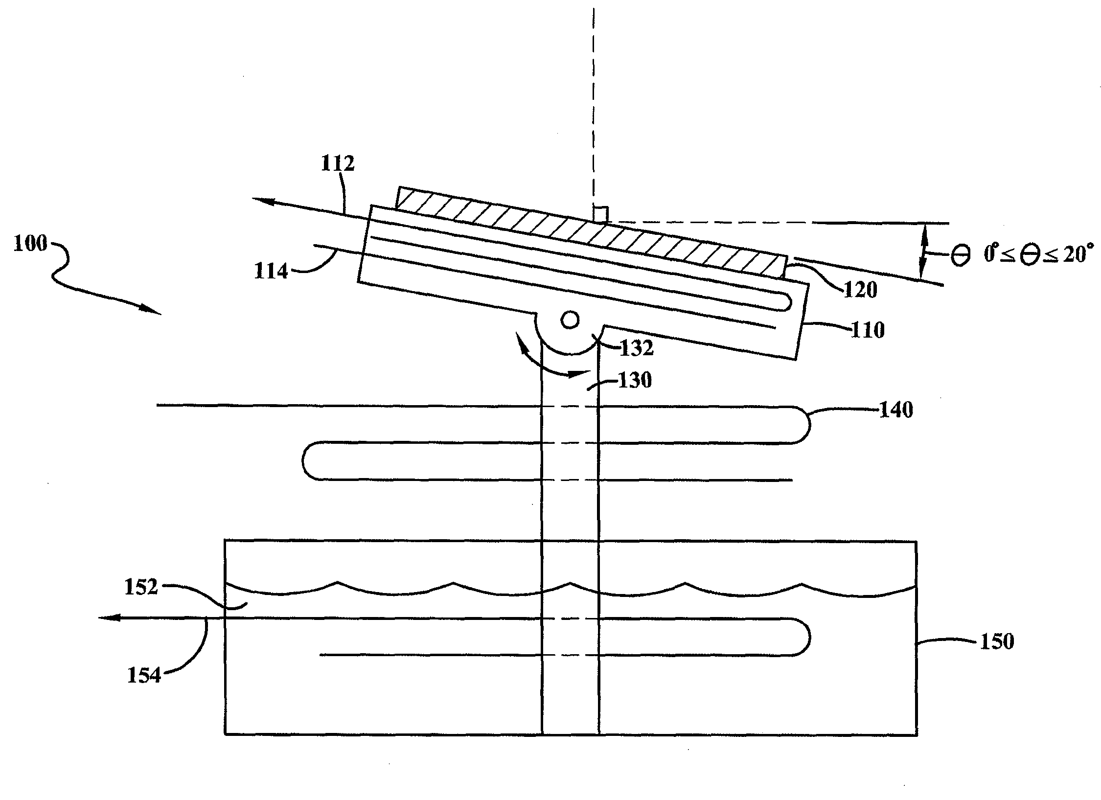
Turning now to the Figures, FIG. 1 is a schematic drawing of a portion of an embodiment 100. The portion 100 comprises a stand for supporting a work piece 120. The stand further comprises a platform member 110 pivotably connected to a base portion 130 at a pivot joint 132. The platform 110 in this example has a range of motion from about 0 degrees to about 20 degrees from horizontal. Furthermore, the platform 110 includes an integrated heating / cooling means 112 comprising metal tubing 112. The tubing 112 is adapted to receive circulating chilled coolant or heated liquids. In this example, the temperature of the platform 110 is sensed using an embedded thermocouple 114. This example also includes an optional air heating element 140. The base 130 is mounted in a reservoir 150 of water 152. The reservoir 150 includes an electric resistance heating element 154 to case evaporation of water 152 into the surrounding atmosphere.

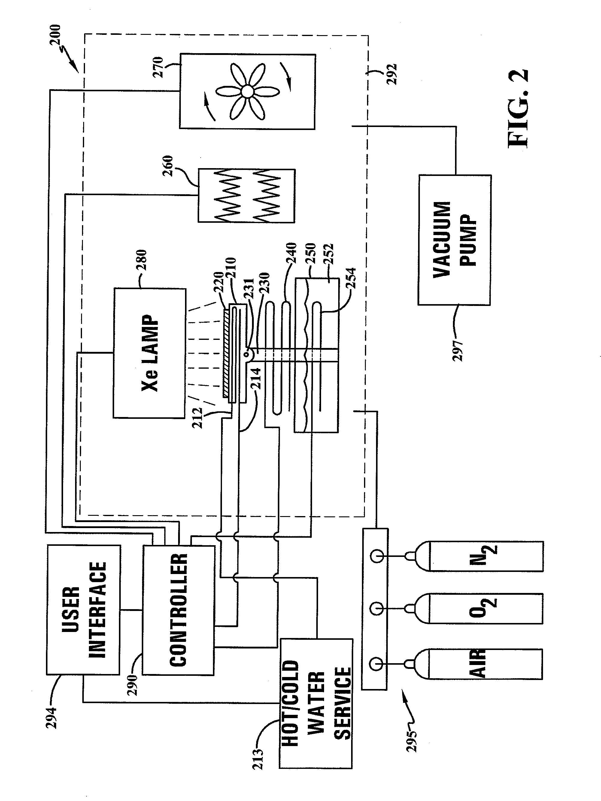
FIG. 2 is a schematic drawing of an embodiment 200 showing the ...

embodiment 200

The embodiment 200 shown in FIG. 2 also includes an optional fan 270 for circulating gases in the weathering chamber 292. While not required, such a fan 270 may be desirable for quickly attaining thermal equilibrium, and preventing the formation of thermal and concentration gradients. According to this embodiment the fan 270 is in electronic controlling communication with the controller 290, and may be, for instance, controlled according to a set program, controlled in response to sensor data received by the controller 290, it may be on continuously, and / or it may be turn on and off manually through the user interface 294.

The embodiment of FIG. 2 also includes a xenon arc lamp 280 for irradiating the work piece 220 with a predetermined spectrum and power of electromagnetic energy. According to this embodiment, the xenon lamp 280 is in electronic controlling communication with the controller 290 and can be operated according to any appropriate power profile including constant power, ...


PUM

PropertyMeasurementUnit
pressureaaaaaaaaaa
output poweraaaaaaaaaa

Abstract

A method for creating condensation in an accelerated weathering device, the method having the step of creating condensation in a weathering chamber of an accelerated weathering device by cooling a surface in the chamber to a temperature that is colder than the dew point of the air inside the chamber. An accelerated weathering device having a weathering chamber and at least one radiant cooling tube that is either touching or less than about 2.5 centimeters away from at least one surface in the weathering chamber so that by passing a fluid through the at least one radiant cooling tube, the temperature of the a least one surface can be decreased as a result of the radiant cooling from the radiant cooling tube.

Description

I. BACKGROUND OF THE INVENTIONA. Field of InventionEmbodiments are directed to devices and methods related to accelerated weathering techniques.B. Description of the Related ArtAccelerated weathering techniques can be understood as tools that provide long-term degradation-behavior data in a shortened timeframe. Automotive manufacturers and related material suppliers typically use accelerated weathering techniques to predict how an automotive material will perform in its actual service environment. Accelerated weathering techniques help to predict a specimen's degradation behavior, and the techniques also help to avoid the delays associated with testing the specimen using only natural outdoor exposure. Accelerated weathering techniques are often applied by accelerated weathering devices. Standard types of accelerated weathering devices are well-known and commercially available. The type of equipment, including light source, temperature capability, humidity capability, and condensatio...

Claims


Application Information

Patent Timeline
Patent Type & Authority Applications(United States)
IPC IPC(8): G01N17/00
CPCG01N17/002
Inventor FITZ, TODD
Owner HONDA MOTOR CO LTD
Learn More