
Fixing unit and image forming apparatus with the same

a technology of fixing unit and image forming apparatus, which is applied in the direction of electrographic process, electric/magnetic/electromagnetic heating, instruments, etc., can solve the problems of degrading the toner image fixed on the sheet, the object is not fixed at the same temperature,

Active Publication Date: 2011-03-03
KYOCERA DOCUMENT SOLUTIONS INC
View PDF5 Cites 10 Cited by
  • Summary
  • Abstract
  • Description
  • Claims
  • Application Information

AI Technical Summary

Benefits of technology

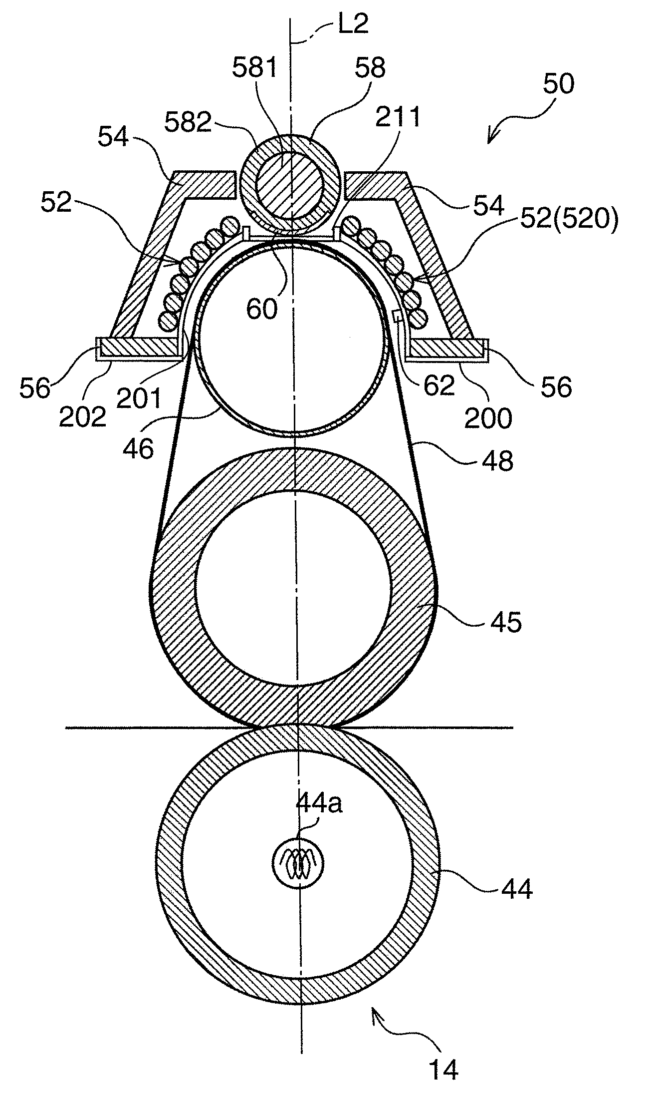
[0046]A fixing unit and an image forming apparatus according to one embodiment are described below with reference to the accompanying drawings. Terms indicating directions such as “upper”, “lower”, “left” and “right” in the following description are simply used for clarification, and so do not limit the present invention in any way. Moreover, descriptions such as “a magnetic tube / a center core near a coil” and “a magnetic tube / a center core near a first element” or similar mean that the magnetic tube / the center core is disposed sufficiently near the coil or the first element so as to contribute to induction-heating. A description “a magnetism shielding plate is disposed near a coil surface” or similar, means that the magnetism shielding plate is placed sufficiently near the coil surface so as to impede magnetic induction of the coil. Furthermore, a term “looped” or similar used in the following description does not only refer to a perfect circular ring shape, but rather is a general term which encompasses an elliptical ring, a square ring, a polygonal ring shape or the like, to indicate any shape of an object defining a preferable closed region.

Problems solved by technology

For example, in the case of the induction-heating type of the fixing apparatus, variation in the distance between the magnetic body and the object to be induction-heated results in irregular temperature over the object, which in turn leads to degrading a toner image fixed on a sheet.

Method used


Image

  • Fixing unit and image forming apparatus with the same
  • Fixing unit and image forming apparatus with the same
  • Fixing unit and image forming apparatus with the same

Examples


Embodiment Construction

[0046]A fixing unit and an image forming apparatus according to one embodiment are described below with reference to the accompanying drawings. Terms indicating directions such as “upper”, “lower”, “left” and “right” in the following description are simply used for clarification, and so do not limit the present invention in any way. Moreover, descriptions such as “a magnetic tube / a center core near a coil” and “a magnetic tube / a center core near a first element” or similar mean that the magnetic tube / the center core is disposed sufficiently near the coil or the first element so as to contribute to induction-heating. A description “a magnetism shielding plate is disposed near a coil surface” or similar, means that the magnetism shielding plate is placed sufficiently near the coil surface so as to impede magnetic induction of the coil. Furthermore, a term “looped” or similar used in the following description does not only refer to a perfect circular ring shape, but rather is a general...


PUM


Abstract

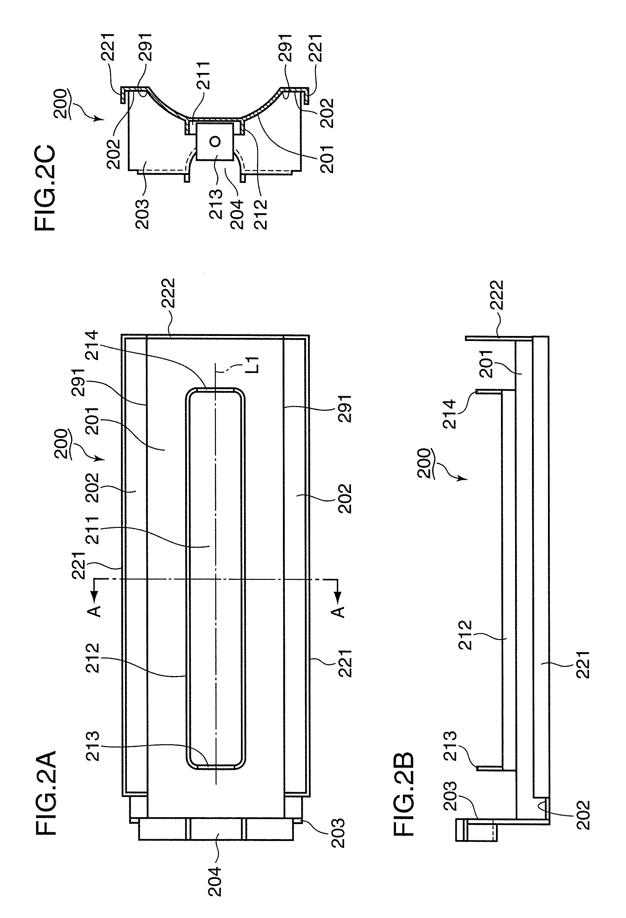
A fixing unit for fixing a toner image onto a sheet passing between a first element and a second element pressed against the first element includes a looped coil surface formed with a coil so that the coil surface generates a magnetic field for induction-heating the first element, the coil surface including an inner edge defining an opening region; an upright wall disposed inside the opening region, an opening being formed in the upright wall; a center core disposed along the opening region, the center core including a conductive shaft and a magnetic tube configured to at least partially cover the conductive shaft; and a nonconductive cap inserted into the opening, the nonconductive cap partially covering the conductive shaft to electrically insulate the coil from the conductive shaft.

Description

BACKGROUND OF THE INVENTION[0001]1. Field of the Invention[0002]The present invention relates to a fixing unit configured to fix a toner image on a sheet, and to an image forming apparatus with the fixing unit.[0003]2. Description of the Related Art[0004]Heating by electromagnetic induction is more rapid and efficient heating manner. Therefore, heating by electromagnetic induction (hereinafter called “induction-heating” or “IH”) is used for various apparatuses. For example, a particular image forming apparatus comprises an induction-heating type of a fixing apparatus.[0005]A distance between a magnetic body through which a magnetic flux passes and an object to be induction-heated in an induction-heating type of an apparatus is a very important parameter. For example, in the case of the induction-heating type of the fixing apparatus, variation in the distance between the magnetic body and the object to be induction-heated results in irregular temperature over the object, which in tur...

Claims


Application Information

Patent Timeline
Patent Type & Authority Applications(United States)
IPC IPC(8): G03G15/20
CPCG03G2215/2032G03G15/2014
Inventor GON, SYOUKOU
Owner KYOCERA DOCUMENT SOLUTIONS INC
Learn More