
High frequency sewing machine

a sewing machine and high frequency technology, applied in the field of high frequency sewing machines, can solve the problems of large number of defective products manufactured, large burn range, and large burn range, and achieve the effect of convenient handling of work materials

Active Publication Date: 2011-03-03
YAMATO SEWING MASCH MFG CO LTD
View PDF8 Cites 1 Cited by
  • Summary
  • Abstract
  • Description
  • Claims
  • Application Information

AI Technical Summary

Benefits of technology

[0009]In view of the foregoing circumstances, the present invention has for its object to provide a high frequency sewing machine which is capable of obtaining the assured uniform bonding strength by using high frequency power, and preventing the manufacturing and processing of defective products having burn, burn holes or the like, and also satisfactorily handling the bonding of curvilinear portions or stretchable fiber clothes.

Problems solved by technology

In the means for enhancing the value of high frequency power, the heat of the enhanced high frequency power is concentratedly exerted on the line or point contact portions, so that the work material is susceptible to insulation breakdown, causing defective portions such as burn and bum holes (scorches).
Particularly, when the work material is a thin fiber cloth that is the object material of the present invention, there is the problem that the burn range is likely to momentarily expand and hence a large number of defective products are manufactured.
In the case of employing the means for decreasing the transfer rate of the paired electrode rollers by setting a low value of high frequency power, there is the problem that processing efficiency is extremely deteriorated.
As disclosed in Japanese Patent No. 4022539, these problems due to the line or point contact occur similarly even when employing the construction where the paired electrode rollers are intermittently rotated, and the occurrence of defective products and the deterioration of processing efficiency are unavoidable.
However, the conventional high frequency sewing machines adapted to linearly transfer a work material in a certain direction with the work material held between the paired electrode rollers cannot sufficiently handle the bonding of the curvilinear portions and the bonding of the stretchable fiber clothes.
That is, the conventional high frequency sewing machines using the paired electrode rollers are suitable for the bonding process of the overlapped portions while linearly transferring unstretchable work material such as resin sheets, but unsuitable for manufacturing and processing the apparel products in which the fiber clothes are used as the object materials, and the bonding of curvilinear portions is frequently performed, and the stretchable materials are frequently used.
Hence, it can be said to be substantially impossible that the conventional high frequency sewing machines are directly applied to the bonding of the fiber clothes.

Method used


Image

  • High frequency sewing machine
  • High frequency sewing machine
  • High frequency sewing machine

Examples


Embodiment Construction

[0034]Embodiments of the present invention are described below with reference to the accompanying drawings.

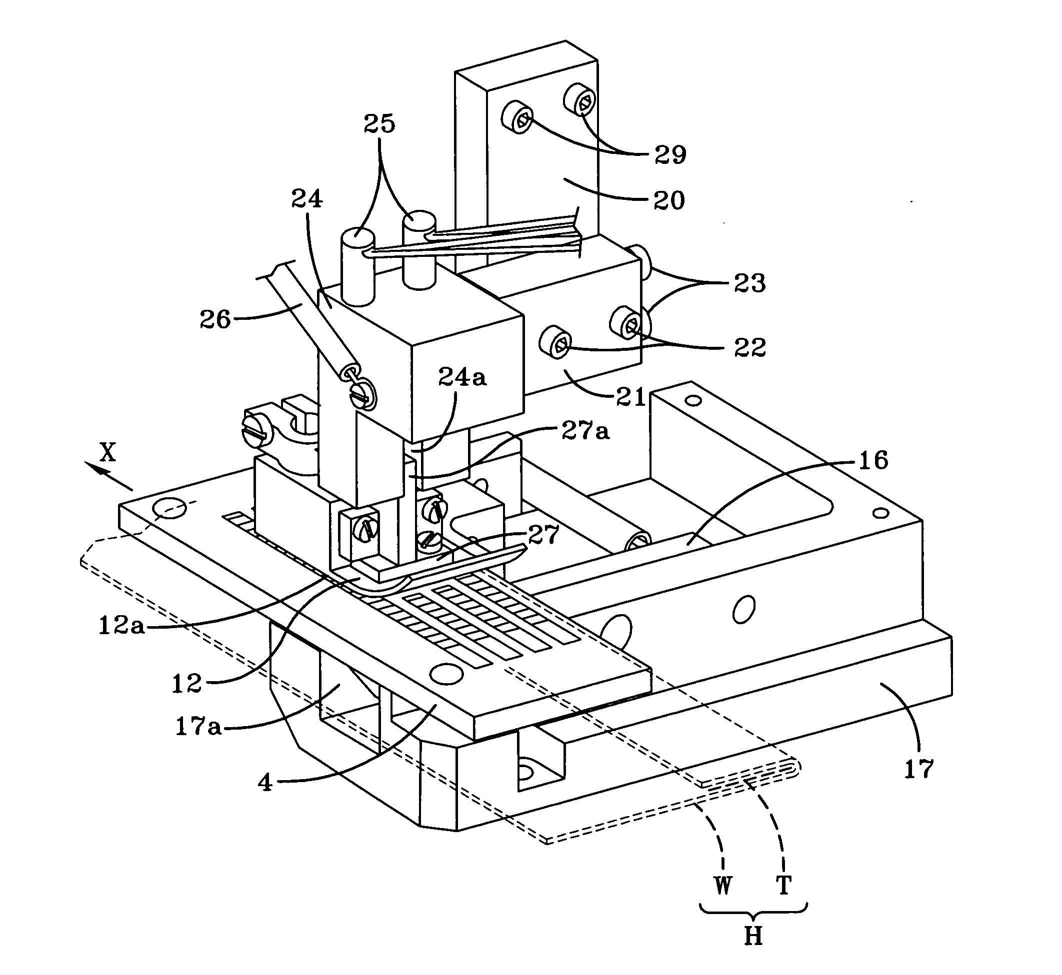
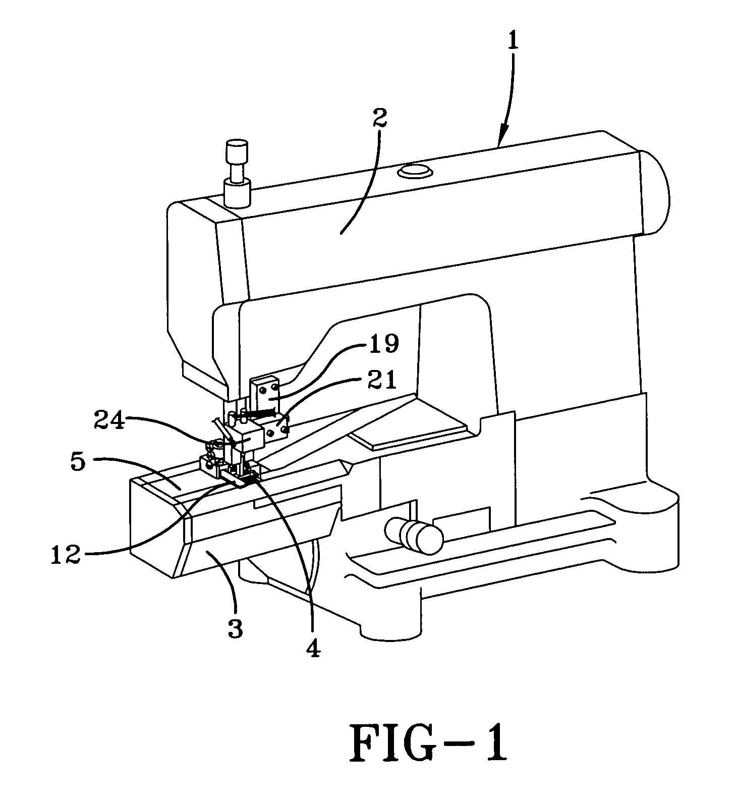
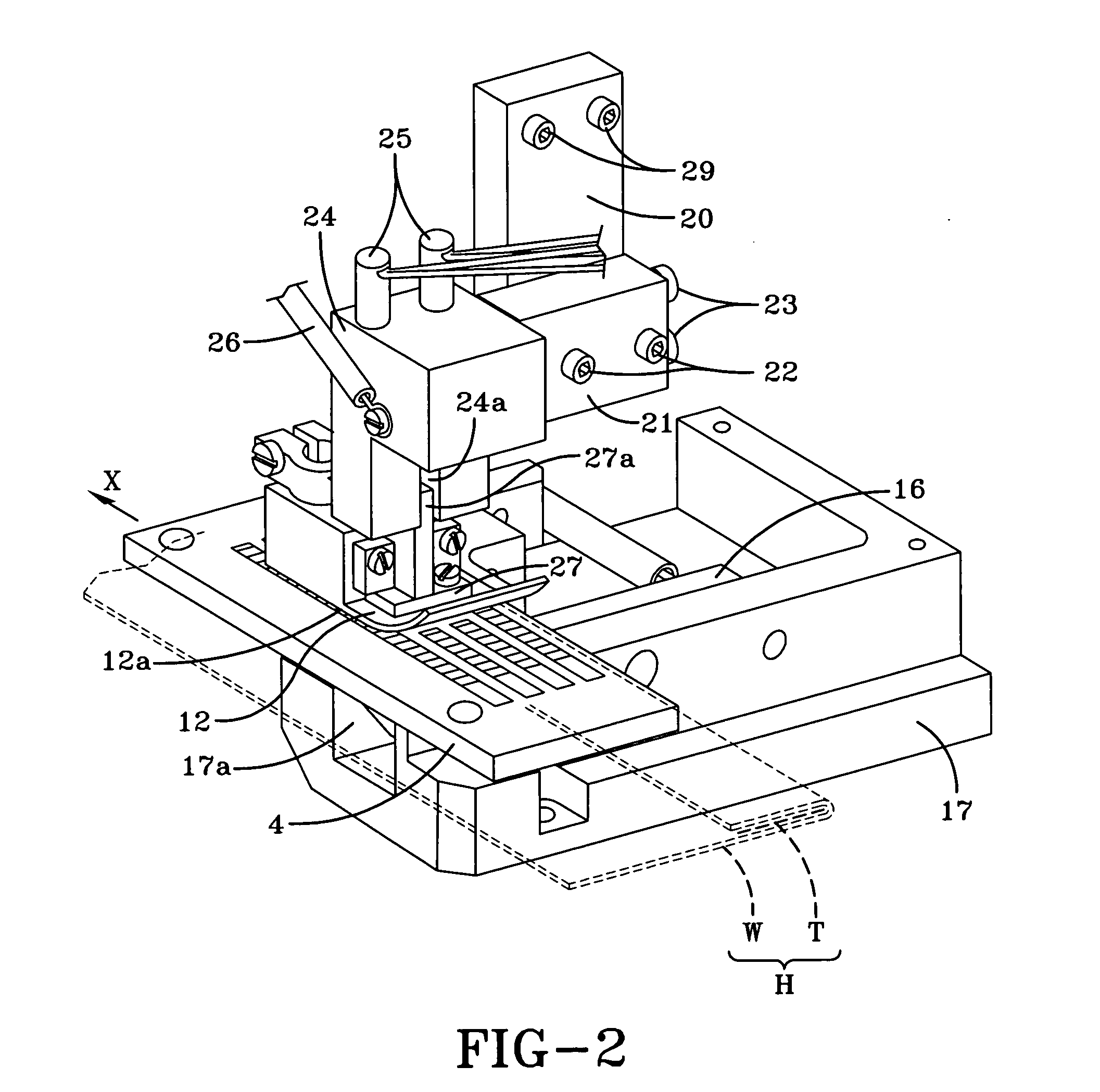
[0035]FIG. 1 is an entire appearance perspective view showing an embodiment of the high frequency sewing machine according to the present invention. FIG. 2 is an enlarged perspective view of important parts of the high frequency sewing machine. FIG. 3 is an enlarged longitudinal sectional view of the important parts of the high frequency sewing machine. In these FIGS. 1 to 3, reference numeral 1 denotes a sewing machine body. The sewing machine body 1 includes a sewing machine arm section 2 and a sewing machine bed section 3.

[0036]The outer shell of the bed section 3 is formed in a substantially square tubular shape when viewed from a direction orthogonal to a processing advance direction X. A work material mounting plate (corresponding to a needle plate in a general sewing machine) 4 for slidably and movably mounting a work material H including a fiber cloth W, and a sliding p...


PUM

PropertyMeasurementUnit
frequencyaaaaaaaaaa
electrical insulating propertiesaaaaaaaaaa
heat resistance propertiesaaaaaaaaaa

Abstract

A high frequency sewing machine for intermittently transferring a work material mounted on a work material mounting plate by means of feed dogs which perform synthetic circular movement in horizontal and vertical directions and which cooperate with a presser foot to effect the continuous bonding of the overlapped portions of a fiber cloth which are continuously bonded together by means of a thermoplastic resin tape held between the overlapped portions of the fiber cloth in the work material to melt under high frequency dielectric heating. High frequency power is applied between a pair of planar electrodes respectively disposed above and below the work material during the time when the transfer by these feed dogs is stopped to effect the melting process. The occurrence of defective products having burn or the like due to heat concentration can be prevented while obtaining assured uniform bonding strength by using the high frequency power. Additionally, the bonding of curvilinear portions and the bonding of stretchable fiber clothes can be sufficiently handled.

Description

CROSS-REFERENCE TO RELATED APPLICATION[0001]This application claims foreign priority based on Japanese Patent Application Serial No. 2010-113646 filed Apr. 23, 2010, which claims priority of Japanese Serial No. 2009-192534 filed Jul. 31, 2009.BACKGROUND OF THE INVENTIONField of the Invention[0002]The present invention relates to a high frequency sewing machine used for manufacturing and processing apparel products (textile products) such as women's clothing, children's clothing and men's clothing in which clothes of natural fibers represented by cotton, wool, silk, or the like, or synthetic fibers represented by polyester, nylon, acryl, or the like (hereinafter referred to as “fiber clothes” in the present application) are used as object materials, and overlapped portions such as the overlapped ends of these fiber clothes are bonded (welded) together through a thermoplastic resin tape melt under high frequency dielectric heating.[0003]As this type of high frequency sewing machine, a...

Claims


Application Information

Patent Timeline
Patent Type & Authority Applications(United States)
IPC IPC(8): B32B37/06
CPCA41D27/245B29C66/961B29C65/18B29C65/305B29C65/32B29C65/5057B29C65/7841B29C65/7891B29C66/135B29C66/431B29C66/729B29C66/8167B29C66/845B29C66/91212B29C66/91231B29C66/91421B29C66/91431B29C65/4815B29C66/836A41H43/04B29C65/04B29C66/006B29C66/71B29C66/81262B29C66/8161B29C66/81871B29K2027/06B29K2033/08B29K2033/12B29K2067/00B29K2077/00
Inventor NAKATA, NORIOOKAMOTO, MASAKISAKAI, ITSUO
Owner YAMATO SEWING MASCH MFG CO LTD
Learn More