
Tunneling magnetoresistive (TMR) read head with low magnetic noise

a magnetic noise and read head technology, applied in nanoinformatics, instruments, record information storage, etc., can solve the problem of no advantage in using the backing layer material in the pinned ferromagnetic layer, and achieve the effect of low mag noise and low magnetic damping

Active Publication Date: 2011-02-24
WESTERN DIGITAL TECH INC
View PDF11 Cites 12 Cited by
  • Summary
  • Abstract
  • Description
  • Claims
  • Application Information

AI Technical Summary

Benefits of technology

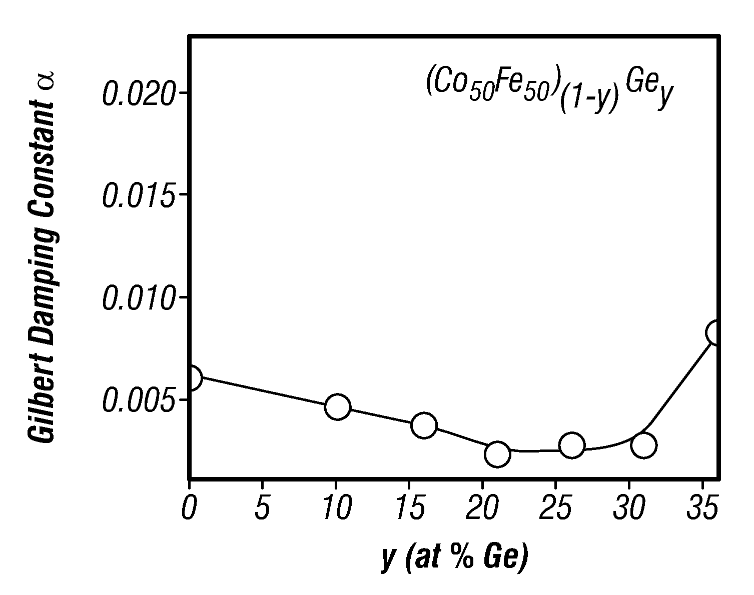
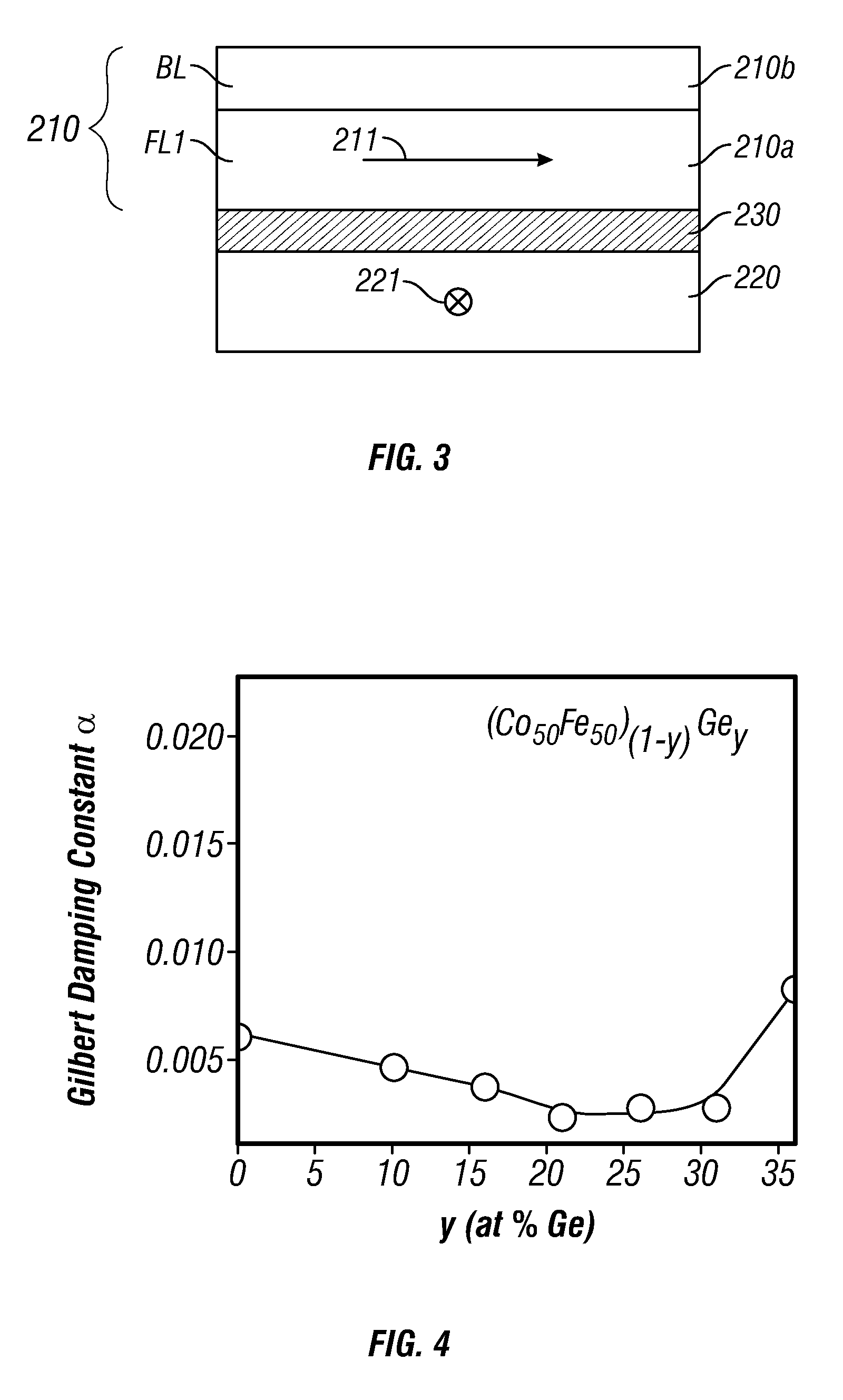
[0008]The invention relates to a TMR device, like a TMR read head, that has low magnetic damping, and thus low mag-noise, as a result of the addition of a ferromagnetic backing layer to the ferromagnetic free layer. The backing layer is located on the surface of the free layer opposite the surface adjacent to the tunneling barrier layer. The backing layer is a ferromagnetic material with a low Gilbert damping constant or parameter a, the well-known dimensionless coefficient in the Landau-Lifshitz-Gilbert equation. The damping parameter a is preferably less than or equal to 0.005. The backing layer has a thickness such that its magnetic moment / area is less than two-thirds the total moment / area of the combined free layer and backing layer.
[0011]The TMR device may also optionally include a thin diffusion barrier or diffusion prevention film between the free layer and the backing layer. This may be desirable to prevent diffusion of Ge or other materials from the backing layer and the diffusion of boron (B) or other materials from the free layer into the backing layer.

Problems solved by technology

Because the purpose of the backing layer is to suppress the mag-noise in the free layer without adversely affecting the performance of the TMR device, there is no advantage to use the material of the backing layer in the pinned ferromagnetic layer.

Method used


Image

  • Tunneling magnetoresistive (TMR) read head with low magnetic noise
  • Tunneling magnetoresistive (TMR) read head with low magnetic noise
  • Tunneling magnetoresistive (TMR) read head with low magnetic noise

Examples


Embodiment Construction

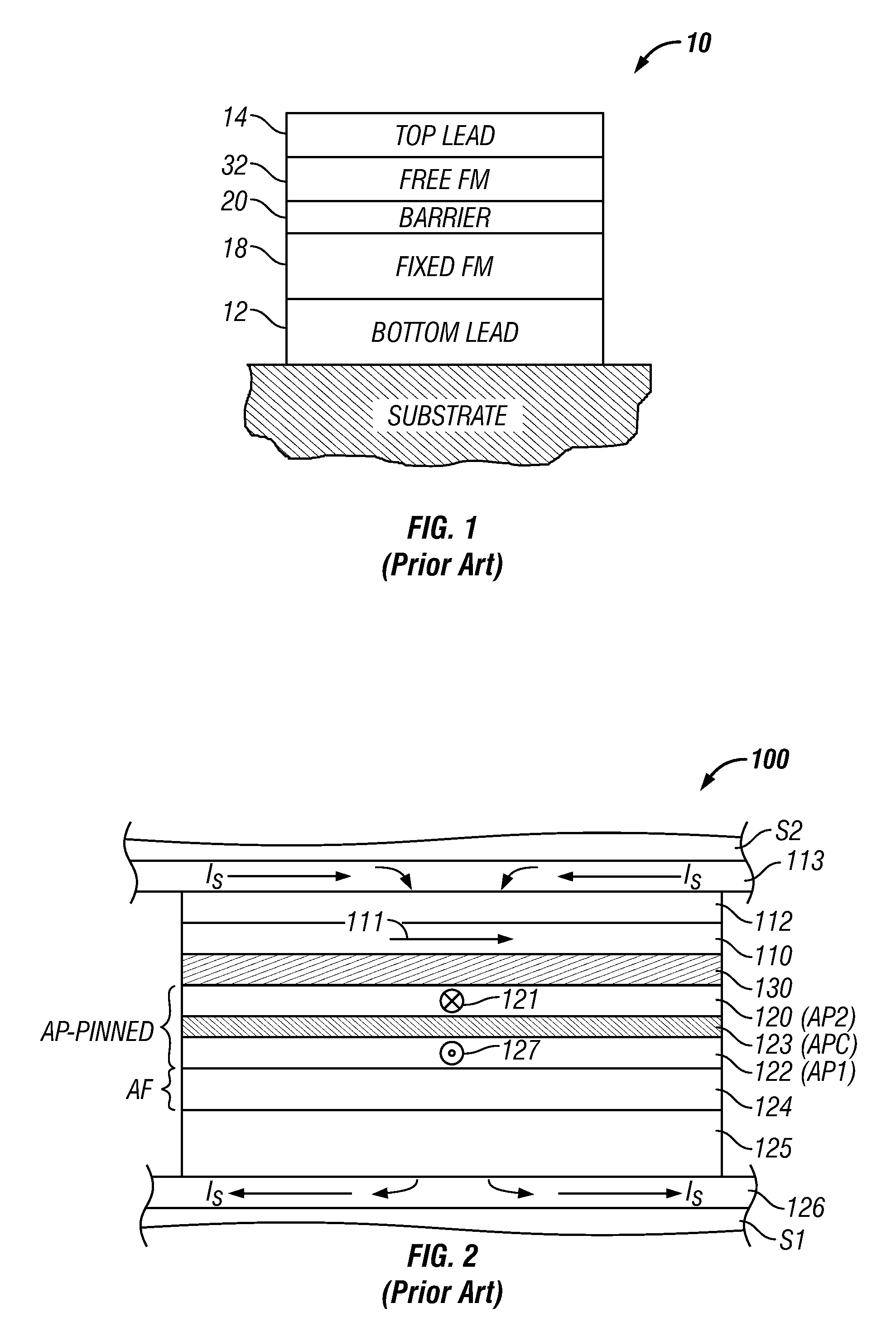
[0017]FIG. 2 is a cross-sectional view illustrating the structure of a prior-art TMR read head 100 like that used in a magnetic recording disk drive. This cross-sectional view is a view of what is commonly referred to as the air-bearing surface (ABS) of the TMR read head 100. The TMR read head 100 includes a sensor stack of layers formed between two ferromagnetic shield layers S1, S2 that are typically made of electroplated NiFe alloy films. The lower shield S1 is typically smoothened by chemical-mechanical polishing (CMP) to provide a smooth surface for the growth of the sensor stack. The sensor stack includes a ferromagnetic reference layer 120 having a pinned magnetization 121 oriented transversely (away from the page), a ferromagnetic free layer 110 having a magnetization 111 that can rotate in the plane of layer 110 in response to transverse external magnetic fields from a recording disk, and an electrically insulating tunneling barrier layer 130, typically made of an oxide, su...


PUM


Abstract

A tunneling magnetoresistance (TMR) device, like a TMR read head for a magnetic recording disk drive, has low magnetic damping, and thus low mag-noise, as a result of the addition of a ferromagnetic backing layer to the ferromagnetic free layer. The backing layer is a material with a low Gilbert damping constant or parameter α, the well-known dimensionless coefficient in the Landau-Lifshitz-Gilbert equation. The backing layer may have a thickness such that it contributes up to two-thirds of the total moment / area of the combined free layer and backing layer. The backing layer may be formed of a material having a composition selected from (CoxFe(100-x))(100-y)Xy, (Co2Mn)(100-y)Xy and (Co2FexMn(1-x))(100-y)Xy, where X is selected from Ge, Al and Si, and (Co2Fe)(100-y)Aly, where y is in a range that results in a low damping constant for the material.

Description

BACKGROUND OF THE INVENTION[0001]1. Field of the Invention[0002]The invention relates generally to tunneling magnetoresistance (TMR) devices, and more particularly to a TMR read head with low magnetic noise for use in magnetic recording disk drives.[0003]2. Description of the Related Art[0004]A tunneling magnetoresistance (TMR) device, also called a magnetic tunneling junction (MTJ) device, is comprised of two ferromagnetic layers separated by a thin insulating tunneling barrier layer. The barrier layer is typically made of a metallic oxide, such as alumina (Al2O3), TiO2, or MgO, that is so sufficiently thin that quantum-mechanical tunneling of charge carriers occurs between the two ferromagnetic layers. This quantum-mechanical tunneling process is electron spin dependent, which means that an electrical resistance measured when applying a sense current across the junction depends on the spin-dependent electronic properties of the ferromagnetic and barrier layers, and is a function o...

Claims


Application Information

Patent Timeline
IPC IPC(8): G11B5/127
CPCB82Y10/00B82Y25/00G01R33/098H01L43/10G11B5/3909H01L43/08G11B5/3906H10N50/85H10N50/10
Inventor CAREY, MATTHEW J.CHILDRESS, JEFFREY R.MAAT, STEFAN
Owner WESTERN DIGITAL TECH INC
Learn More