Ion beam monitoring arrangement
a technology of monitoring arrangement and ion beam, which is applied in the direction of thermometer details, discharge tube/lamp details, and test/measurement of semiconductor/solid-state devices, etc. it can solve the problems of large aperture of faraday, large disadvantages, and duplication of detectors with associated complexity and expense, and achieve the effect of changing the performance characteristics of the device being implanted
- Summary
- Abstract
- Description
- Claims
- Application Information
AI Technical Summary
Benefits of technology
Problems solved by technology
Method used
Image
Examples
first embodiment
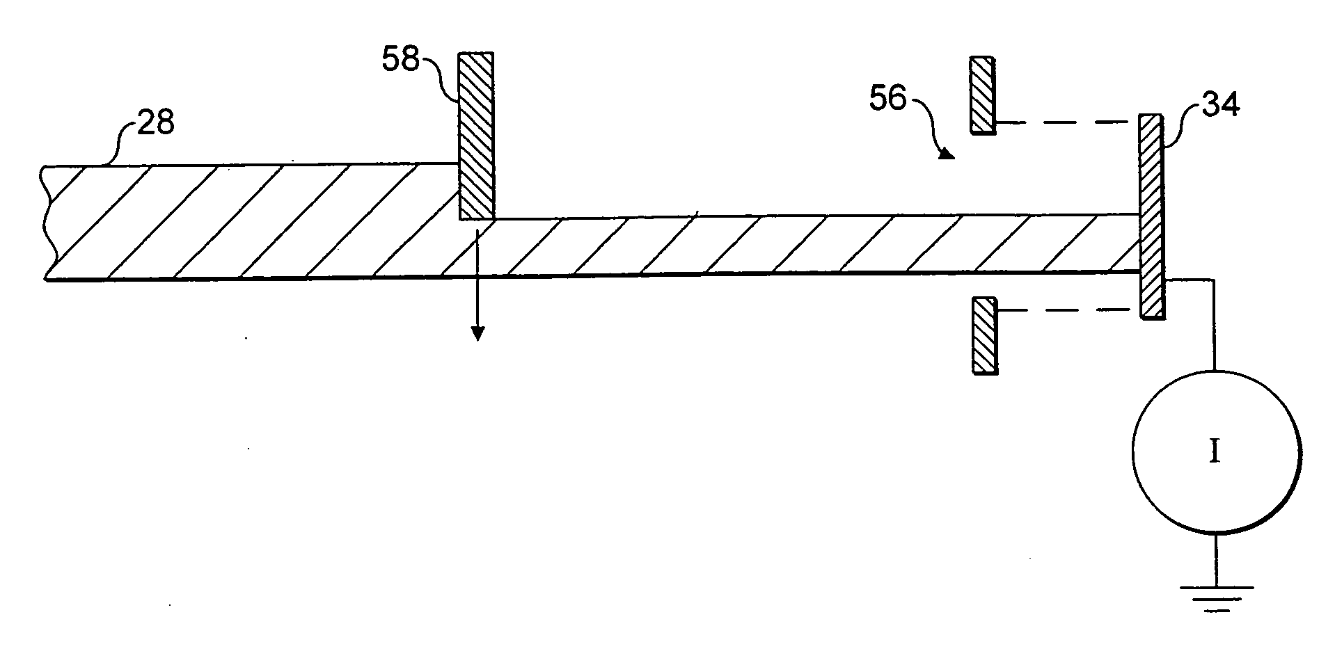
[0085]It is convenient to use the substrate support to move the shield 58 as it already has the ability to move along the X- and Y-coordinate directions. A first embodiment is shown in FIG. 4 where the support arm 38 itself is used as a shield 58. In this embodiment, the support arm 38 has a flat lower edge that extends along the X-coordinate direction. Accordingly, the chuck 36 can be driven across the process chamber 30 past the ion beam 28 such that the flat lower edge of the support arm 38 is located above the ion beam 28. In this arrangement, passage of the ion beam 28 to the beamstop 34 is unobstructed and the Faraday 34 measures the total ion beam flux. The support arm 38 is then driven downwards into the ion beam 28 such that the flat lower edge progressively occludes the ion beam 28.
[0086]The ion beam 28 striking the support arm 38 will cause localised heating and also possibly ablation of material. In either event, the result is the possibility of contamination of a wafer ...
second embodiment
[0093]While the embodiment of FIG. 4 is particularly simple, it allows only the profile of the ion beam 28 in the Y-coordinate direction to be determined. A second embodiment is shown in FIG. 5 that allows the profile in both X- and Y-coordinate directions to be measured. The chuck 36 is modified to include straight edges 60 provided at its outermost and bottommost extremes such that they extend along the Y- and X-coordinate directions respectively. The edges 60 may be covered or coated with semiconductor material or graphite (or similar) to reduce contamination problems.
[0094]The edges 60 may be driven into the ion beam 28 from either side of the ion beam 28 or from above the ion beam 28 to cause progressive occlusion. As per the embodiment of FIG. 4, the controller records the change in measured ion flux along with the position of the chuck 36 and determines the ion flux profile therefrom. Driving the chuck 36 vertically will allow the profile in the Y-coordinate direction to be d...
PUM
| Property | Measurement | Unit |
|---|---|---|
| diameter | aaaaa | aaaaa |
| diameter | aaaaa | aaaaa |
| depth | aaaaa | aaaaa |
Abstract
Description
Claims
Application Information
 - Generate Ideas
- Intellectual Property
- Life Sciences
- Materials
- Tech Scout
- Unparalleled Data Quality
- Higher Quality Content
- 60% Fewer Hallucinations
Browse by: Latest US Patents, China's latest patents, Technical Efficacy Thesaurus, Application Domain, Technology Topic, Popular Technical Reports.
© 2025 PatSnap. All rights reserved.Legal|Privacy policy|Modern Slavery Act Transparency Statement|Sitemap|About US| Contact US: help@patsnap.com


