
Exhaust purification apparatus for internal combustion engine

a technology for purifying apparatus and internal combustion engine, which is applied in mechanical apparatus, machine/engine, electric control of exhaust treatment, etc., can solve the problems of difficult to always optimally control the injection amount of reducing agent, variable purification performance between individual units, etc., and achieves suppressing ammonia, and high nox reduction rate

Inactive Publication Date: 2011-02-24
HONDA MOTOR CO LTD
View PDF5 Cites 30 Cited by
  • Summary
  • Abstract
  • Description
  • Claims
  • Application Information

AI Technical Summary

Benefits of technology

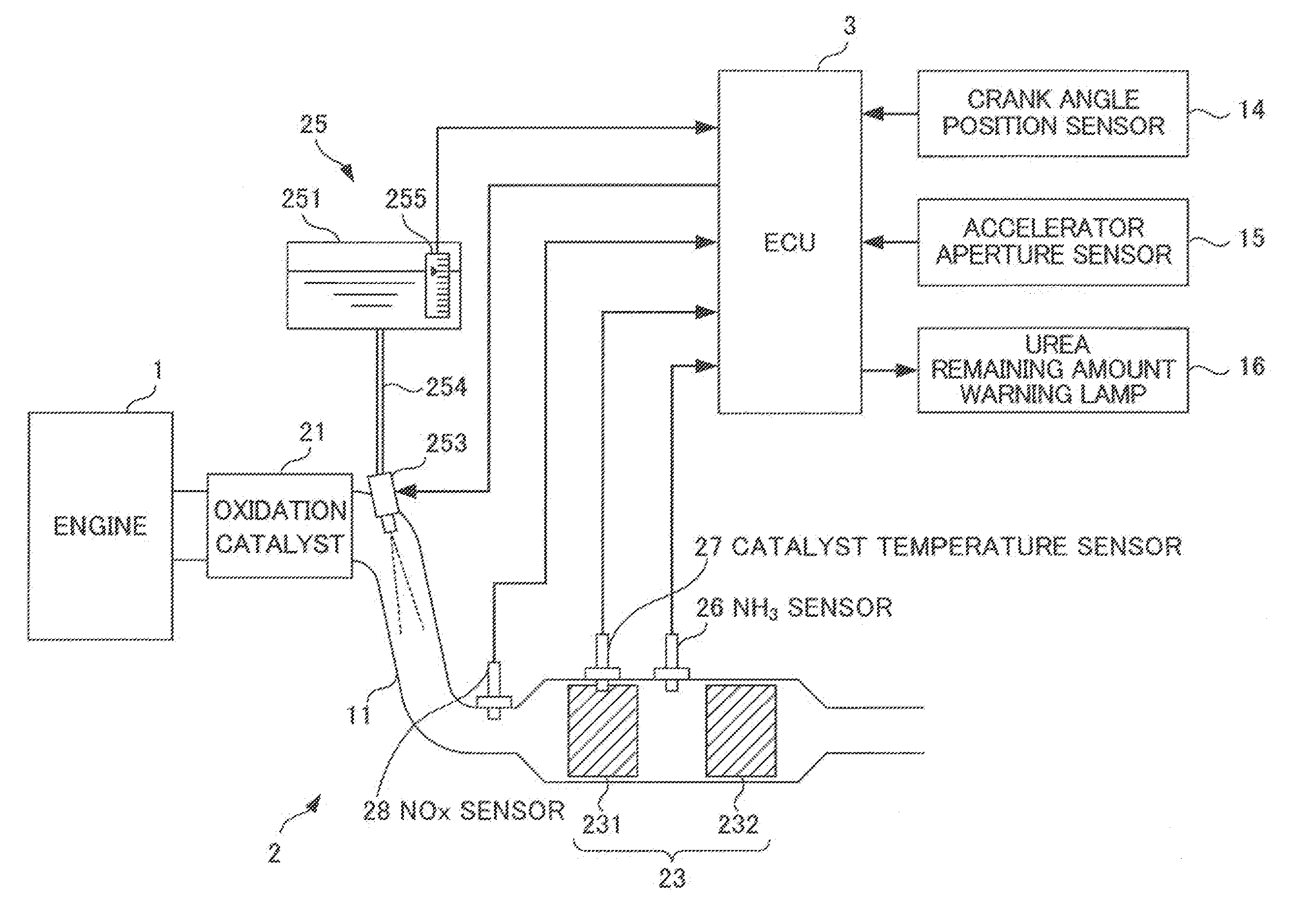
[0028]According to the invention as described in the first aspect, a first selective reduction catalyst and a second selective reduction catalyst are provided in sequence towards a downstream side in the exhaust channel, and further, a reducing agent supply means for supplying reducing agent from an upstream side of the first selective reduction catalyst and the second selective reduction catalyst, and an ammonia concentration detection means for detecting an ammonia concentration between the first selective reduction catalyst and the second selective reduction catalyst are provided. Then, a control input is calculated for controlling so that the ammonia concentration detected by way of the ammonia concentration detection means becomes a value greater than “0”, and the supply amount of reducing agent from the reducing agent supply means is determined to be include such a control input.
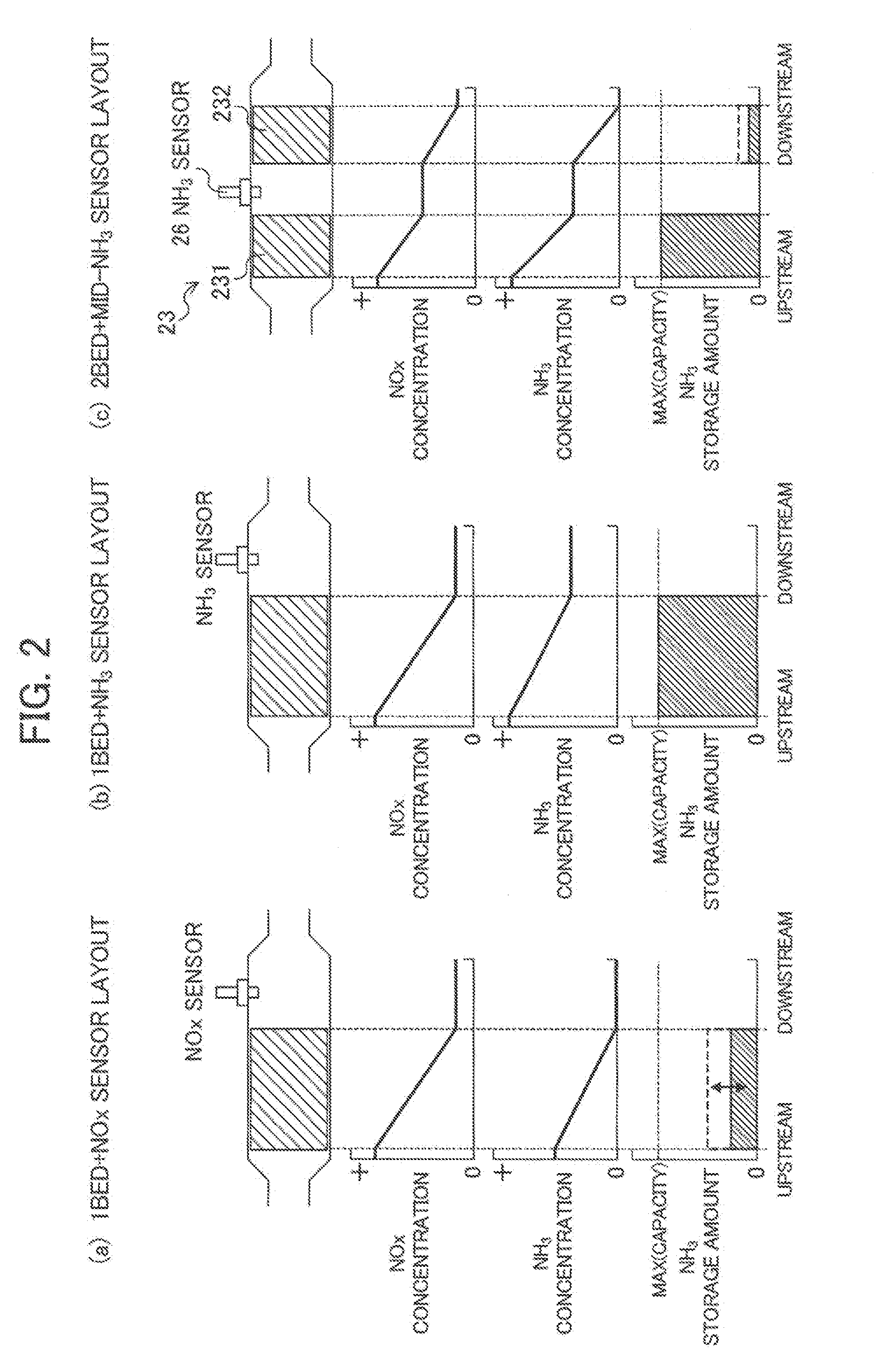
[0029]With this, a state in which ammonia flows out from the first selective reduction catalyst, i.e. a state in which ammonia is sufficiently stored in the first selective reduction catalyst, is held, and thus it is possible to maintain a high NOx reduction rate. In particular, the NOx reduction rate during transition until the generation of ammonia ends can be maintained to be high due to ammonia stored in the first selective reduction catalyst, even if in a case in which NOx of a great amount is temporarily generated by sudden change in the operating state of the internal combustion engine such that the generation of ammonia for reducing this NOx cannot keep pace.
[0030]In addition, in this case, although ammonia slip occurs in the first selective reduction catalyst, the ammonia discharged is either stored in the second selective reduction catalyst or consumed in the reduction of NOx in the second selective reduction catalyst. With this, it is possible to maintain a high NOx reduction rate, as well as suppressing ammonia from being discharged to furthest downstream of the selective catalyst.
[0031]Incidentally, the storage capacity of the selective reduction catalyst changes according to the temperature of this selective reduction catalyst. More specifically, the storage capacity becomes smaller with the temperature of the selective reduction catalyst rising. Therefore, in a state in which ammonia is sufficiently stored in the first selective reduction catalyst as described above, if the temperature thereof suddenly rises, the first storage capacity will suddenly decreases, and the ammonia that had been stored will be discharged to the second selective reduction catalyst.
[0032]According to the invention as described in the second aspect, the second storage capacity of the second selective reduction catalyst is set to be larger than a difference between a maximum and minimum of the first storage capacity of the first selective reduction catalyst. With this, even in a case of the temperature of the first selective reduction catalyst suddenly rising by the operating state of the internal combustion engine transitioning from a low load operating state to a high load operating state, and ammonia being discharged from the first selective reduction catalyst to a downstream side thereof, this ammonia can be stored by the second selective reduction catalyst. With this, ammonia can be further suppressed from discharging to the furthest downstream of the selective reduction catalyst.
[0033]Incidentally, the NOx reduction rate of the selective reduction catalyst has a smaller response lag and higher sensitivity than the ammonia slip of this selective reduction catalyst to the supply amount of the reducing agent. In other words, if the supply amount of reducing agent decreases in order to suppress ammonia slip, for example, there is a problem in that the NOx reduction rate of the selective reduction catalyst declines drastically.

Problems solved by technology

In addition, there is variability in purification performance between individual units.
Therefore, it is difficult to always optimally control the injection amount of reducing agent with exhaust purification apparatuses such as those exemplified in Patent Documents 1 and 2.

Method used


Image

  • Exhaust purification apparatus for internal combustion engine
  • Exhaust purification apparatus for internal combustion engine
  • Exhaust purification apparatus for internal combustion engine

Examples


Embodiment Construction

sor for the conventional exhaust purification apparatus.

EXPLANATION OF REFERENCE NUMERALS

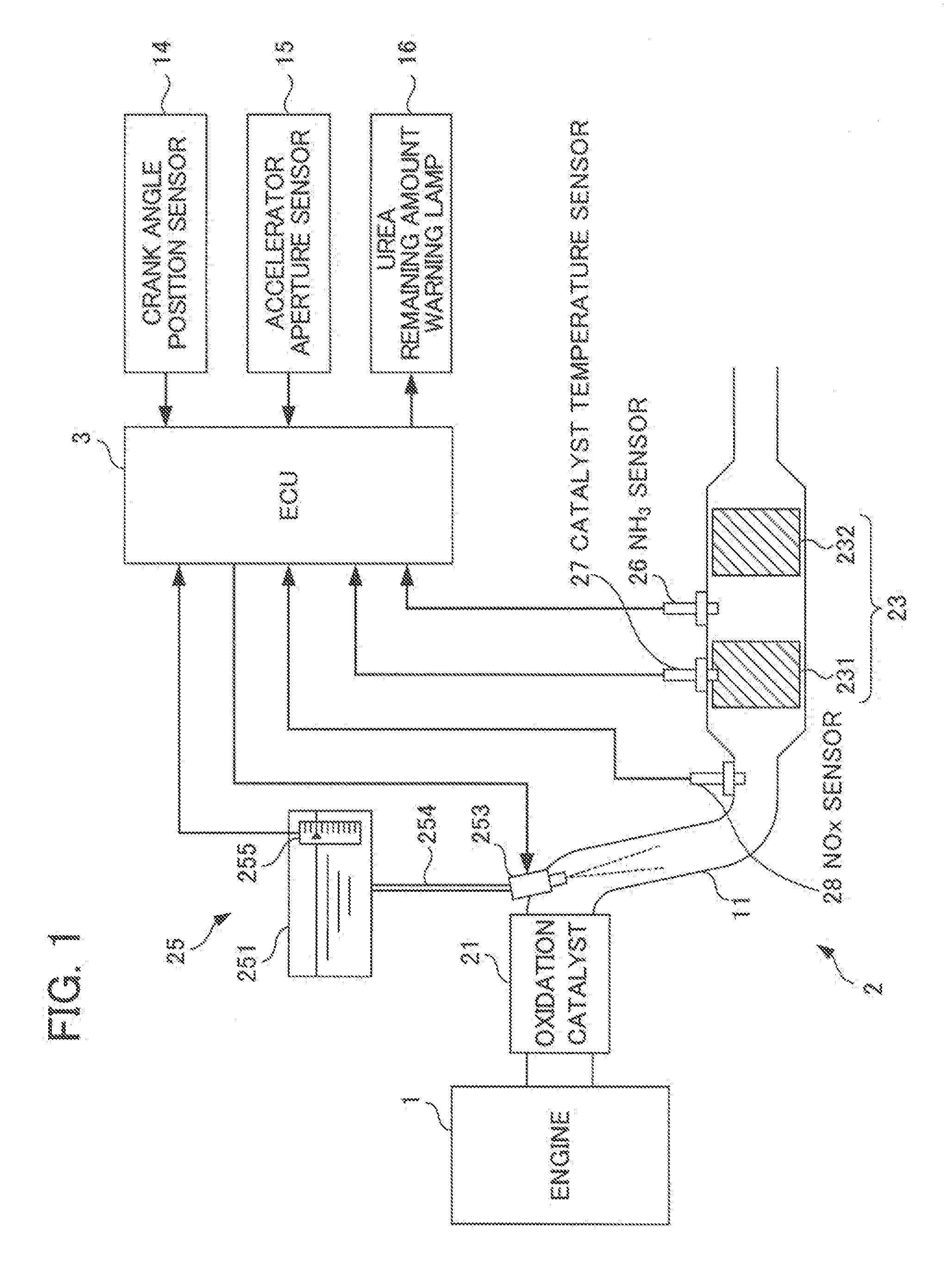
[0079]1 engine (internal combustion engine)[0080]11 exhaust channel (exhaust channel)[0081]2 exhaust purification apparatus[0082]23 urea selective reduction catalyst (selective reduction catalyst)[0083]231 first selective reduction catalyst[0084]232 second selective reduction catalyst[0085]25 urea injection device (reducing agent supply means)[0086]26 ammonia sensor (ammonia concentration detection means)[0087]28 NOx sensor[0088]3 electronic control unit (first control input calculation means, second control input calculation means, third control input calculation means, reducing agent supply amount determination means, target ammonia concentration setting means)[0089]4 feed-back controller (first control input calculation means, target ammonia concentration setting means)[0090]41 target ammonia concentration setting portion (target ammonia concentration setting means)[0091]42 sliding-mode contr...


PUM


Abstract

An exhaust purification apparatus for internal combustion engine having a selective reduction catalyst that while maintaining a high NOx reduction ratio, inhibits any ammonia discharge downstream of the selective reduction catalyst. In the exhaust purification apparatus (2), a urea selective reduction catalyst (23) comprises a first selective reduction catalyst (231) and, provided downstream of the first selective reduction catalyst (231) in an exhaust passageway (11), a second selective reduction catalyst (232). Further, the exhaust purification apparatus (2) includes a urea injection unit (25) for feeding of a reducing agent upstream of the urea selective reduction catalyst (23) in the exhaust passageway (11) and an ammonia sensor (26) for detection of the ammonia concentration at a site between the first selective reduction catalyst (231) and the second selective reduction catalyst (232) in the exhaust passageway (11). The rate of urea injection, GUREA, by the urea injection unit (25) is determined so that the value of ammonia concentration, NH3CONS, detected by the ammonia sensor (26) is greater than “0.”

Description

TECHNICAL FIELD[0001]The present invention relates to an exhaust purification apparatus for an internal combustion engine, and particularly relates to an exhaust purification apparatus for an internal combustion engine that is provided with a selective reduction catalyst that reduces NOx in the exhaust under the presence of a reducing agent.BACKGROUND ART[0002]Conventionally, as one of the exhaust purification apparatuses that purify NOx in exhaust, an apparatus has been proposed in which a selective reduction catalyst is provided in an exhaust channel that selectively reduces NOx in the exhaust by adding a reducing agent. For example, with the selective reduction catalyst of a urea addition type using urea water as the reducing agent, ammonia is generated from the urea thus added, and NOx in the exhaust is selectively reduced by this ammonia.[0003]With such a selective reduction catalyst, in a case of the injection amount of the reducing agent being less than an optimum amount, the...

Claims


Application Information

Patent Timeline
IPC IPC(8): F01N9/00F01N3/10
CPCF01N3/208F01N2560/021F01N2570/18F01N2610/02F01N2610/146F01N13/0093F01N2900/0411F01N2900/1402F01N2900/1622Y02T10/24F01N13/0097F01N2900/0408Y02T10/12
Inventor YASUI, YUJIKAWASUMI, IKUEFISCHER, MICHAEL
Owner HONDA MOTOR CO LTD
Learn More