Electromagnetic-wave-absorbing film and electromagnetic wave absorber comprising it
a technology of electromagnetic waves and film, which is applied in the field of electromagnetic wave absorber and film comprising electromagnetic waves, can solve the problems of not being able to absorb electromagnetic waves in a wide frequency range without, being difficult to be disposed in the apparatus casing, and being heavy and bulky, and achieve excellent electromagnetic wave absorbability
- Summary
- Abstract
- Description
- Claims
- Application Information
AI Technical Summary
Benefits of technology
Problems solved by technology
Method used
Image
Examples
example 1
[0091]A 0.05-μm-thick aluminum layer was formed on a surface of a biaxially oriented polyethylene terephthalate (PET) film [thickness: 12 μm, dielectric constant: 3.2 (1 MHz), dissipation factor: 1.0% (1 MHz), melting point: 265° C., and glass transition temperature: 75° C.] by a vacuum deposition method, to produce a composite film. Using the apparatus shown in FIGS. 5(a) and 5(b), a roll 2 having electroplated fine diamond particles having a particle size distribution of 50-80 μm was brought into sliding contact with the aluminum layer of the composite film 1′ under the following conditions.
[0092]Moving speed of composite film 1′: 10 in / minute,
[0093]Peripheral speed of roll 2: 350 m / minute,
[0094]Tension of composite film 1′: 0.1 kgf / cm width, and
[0095]Winding angle θ of film: 30°.
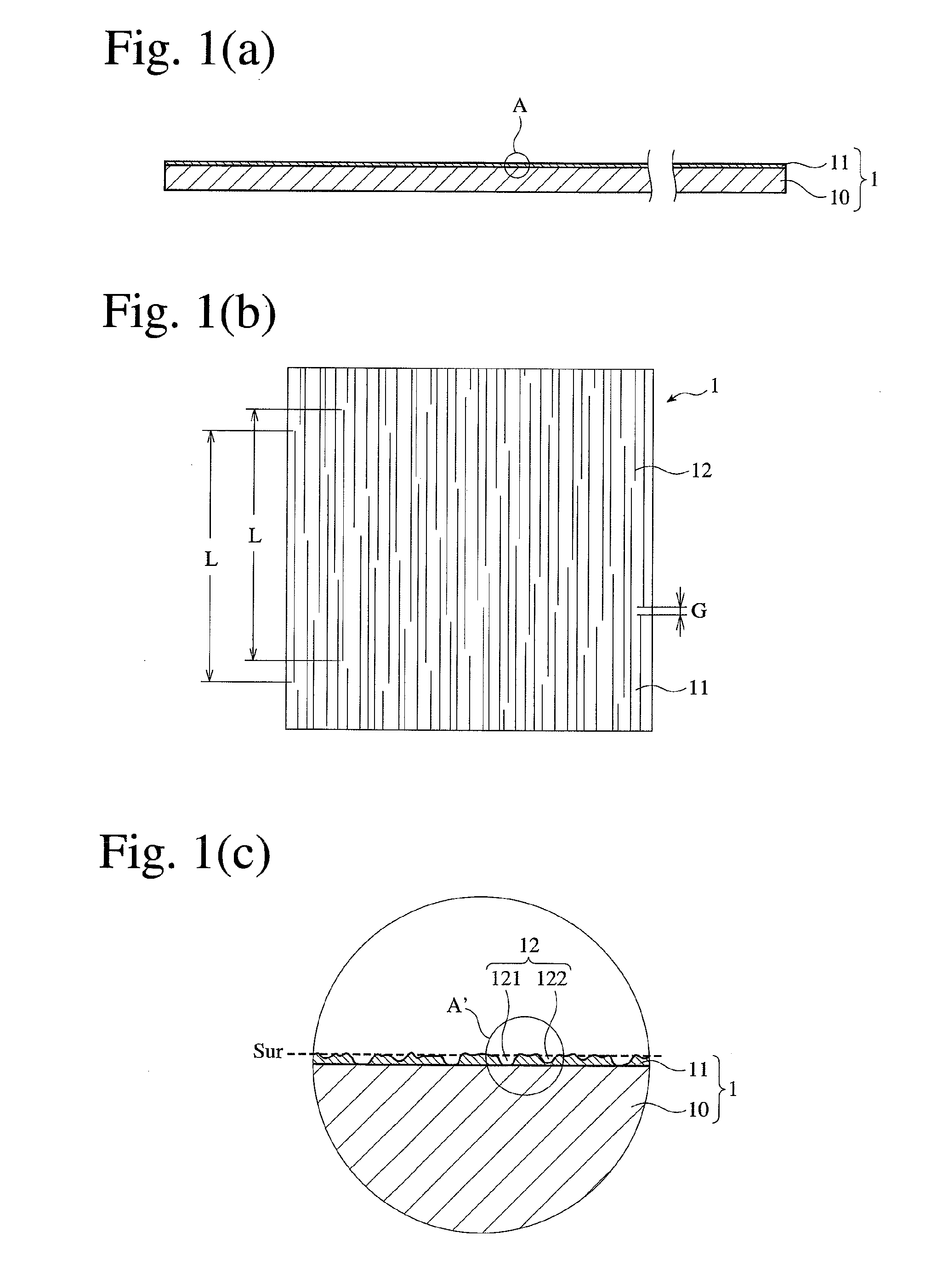
[0096]Optical photomicrographical observation revealed that the resultant electromagnetic-wave-absorbing film had the following linear scratches:
[0097]Range of widths W: 0.5-5 μm,
[0098]Average width Way: ...
example 2
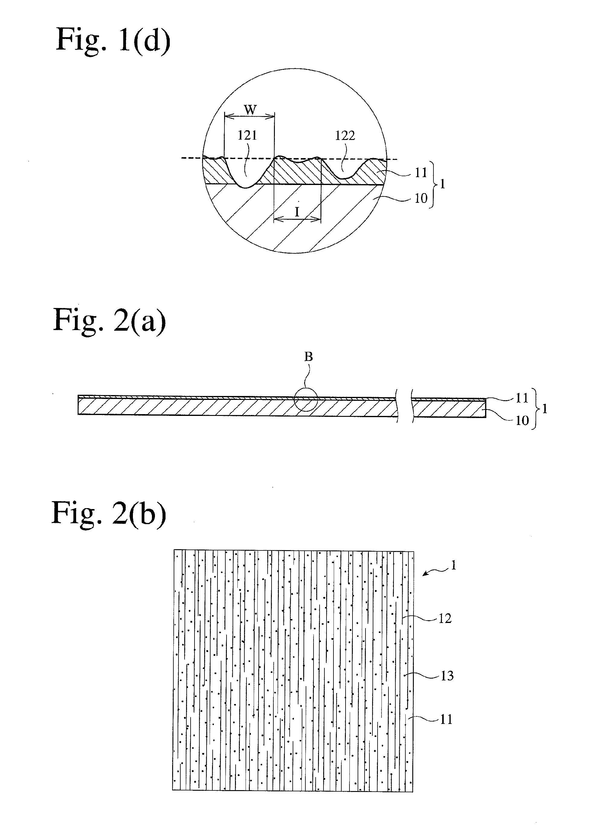
[0104]The same electromagnetic-wave-absorbing film as in Example 1 except for having fine pores was produced. The fine pores had an average opening diameter of 3 μm, and an average density of 5×10⁴ / cm2. The surface resistance of this electromagnetic-wave-absorbing film was 900 Ω / square and 15 Ω / square, respectively, in directions perpendicular and parallel to the linear scratches. The electromagnetic wave absorbability measured in the same manner as in Example 1 is shown in FIG. 18.
example 3
[0105]An electromagnetic wave absorber was obtained by disposing the electromagnetic-wave-absorbing films of Examples 1 and 2 in parallel with a gap of 5.0 mm such that their linear scratches were substantially perpendicular to each other, and arranged between the antennas 50, 60 with the electromagnetic-wave-absorbing film of Example 1 on the side of the antenna 50, to evaluate the electromagnetic wave absorbability in the same manner as in Example 1. The results are shown in FIG. 19.
PUM
| Property | Measurement | Unit |
|---|---|---|
| Length | aaaaa | aaaaa |
| Length | aaaaa | aaaaa |
| Length | aaaaa | aaaaa |
Abstract
Description
Claims
Application Information
 - R&D
- Intellectual Property
- Life Sciences
- Materials
- Tech Scout
- Unparalleled Data Quality
- Higher Quality Content
- 60% Fewer Hallucinations
Browse by: Latest US Patents, China's latest patents, Technical Efficacy Thesaurus, Application Domain, Technology Topic, Popular Technical Reports.
© 2025 PatSnap. All rights reserved.Legal|Privacy policy|Modern Slavery Act Transparency Statement|Sitemap|About US| Contact US: help@patsnap.com


