
Analytical method for use in optimizing dimensional quality in hot and cold rollling mills

a technology of hot and cold rolling mills and analytical methods, applied in the direction of measuring devices, profile control devices, instruments, etc., can solve the problems of inability to adapt to the intricacies of cluster-type and related modern rolling stand configuration, inability to predict and/or control and inability to accurately predict the profile and flatness of rolled metal. to achieve the effect of reducing the number of calculations the arithmetic logic uni

Inactive Publication Date: 2011-02-10
WRIGHT STATE UNIVERSITY
View PDF14 Cites 9 Cited by
  • Summary
  • Abstract
  • Description
  • Claims
  • Application Information

AI Technical Summary

Benefits of technology

This approach allows for precise and rapid prediction and control of strip profile and flatness, reducing computational time and improving accuracy, enabling real-time adjustments and dynamic analysis, thus enhancing the quality of rolled metal strips and reducing equipment damage.

Problems solved by technology

Each of these conventional methods used to predict and / or control rolled metal profile and flatness are deficient due to one or more general shortcomings.
Because of the inherent complexity of typical rolling mills (especially cluster-type rolling stand configurations), few of the conventional analytical methods readily encompass the details necessary to attain an accurate result, while a more simplistic method, such as the single beam on elastic foundation method, is not well-suited to the intricacies of cluster-type and related modern rolling stand configurations.
Of the methods that have been devised for use in cluster-type mills, such as the influence coefficient / point match and transport matrix methods, excessively complex models with limited transferability have arisen.
Due to the number of iterations and associated computation time, the influence coefficient / point match method is not directly suitable for on-line and related real-time prediction and control in rolling mills.
While the transport matrix method has been used on-line for vertical-stack (non cluster type) rolling mills, it is also not suitably fast enough for mills having relatively large numbers of rolls, such as the 20-roll Sendzimir cluster-type mill.
Large-scale finite element methods require the most computation time of any conventional method.
Even for off-line studies, wherein execution time is not critical, the finite element method's use is questionable because of the convergence issues and lengthy computation time associated with contact-type structural analyses.
The third general shortcoming is insufficient accuracy.
The single beam on elastic foundation method is inaccurate in all instances because it neglects shear deformation of the work rolls and considers deflection of the backup rolls (shear, bending, and flattening) as a constant elastic foundation.
The influence coefficient / point match method and transport matrix method suffer inaccuracy because the strip profile is predicted in a piecewise continuous (“connect-the-dots”) manner, with accuracy conditional upon a relatively large number of closely-spaced nodes.
As node count is increased to improve accuracy, computation time and speed are adversely affected.
Since pattern recognition / heuristic models are non-physics based, they exhibit deficiencies in both trend and accuracy in the absence of training with actual data.
Such required data may not be available prior to commissioning a strip profile and flatness control system, particularly for newly-started rolling mills.
The fifth general shortcoming is the inability of any of the conventional methods to predict the dynamic deflection behavior of the rolling mills.
With the exception of large-scale commercial finite element methods, none of the conventional methods previously described are able to predict and control dynamic deflection of rolling mill stands.
While the conventional approaches are currently being employed, their effectiveness is limited by one or more of the aforementioned problems and disadvantages.

Method used


Image

  • Analytical method for use in optimizing dimensional quality in hot and cold rollling mills
  • Analytical method for use in optimizing dimensional quality in hot and cold rollling mills
  • Analytical method for use in optimizing dimensional quality in hot and cold rollling mills

Examples


Embodiment Construction

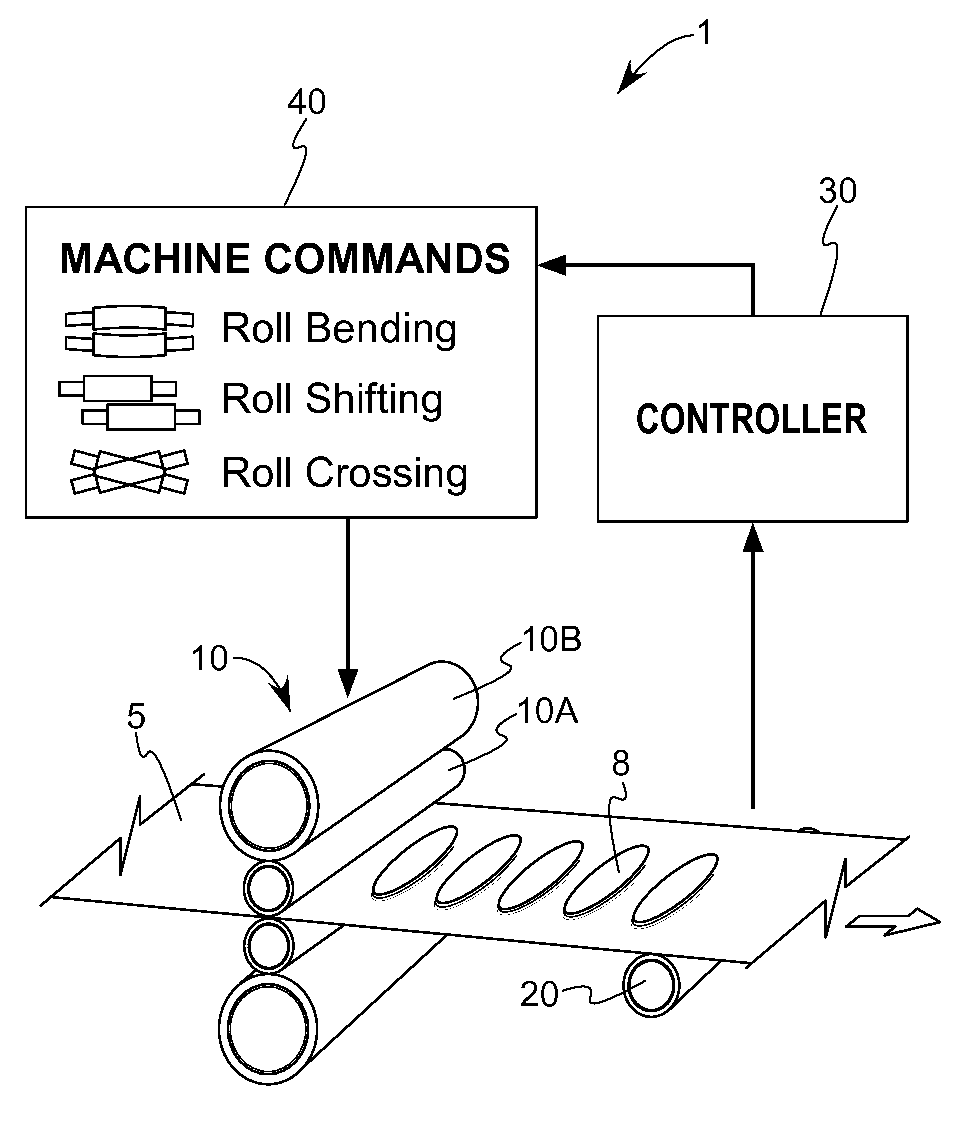
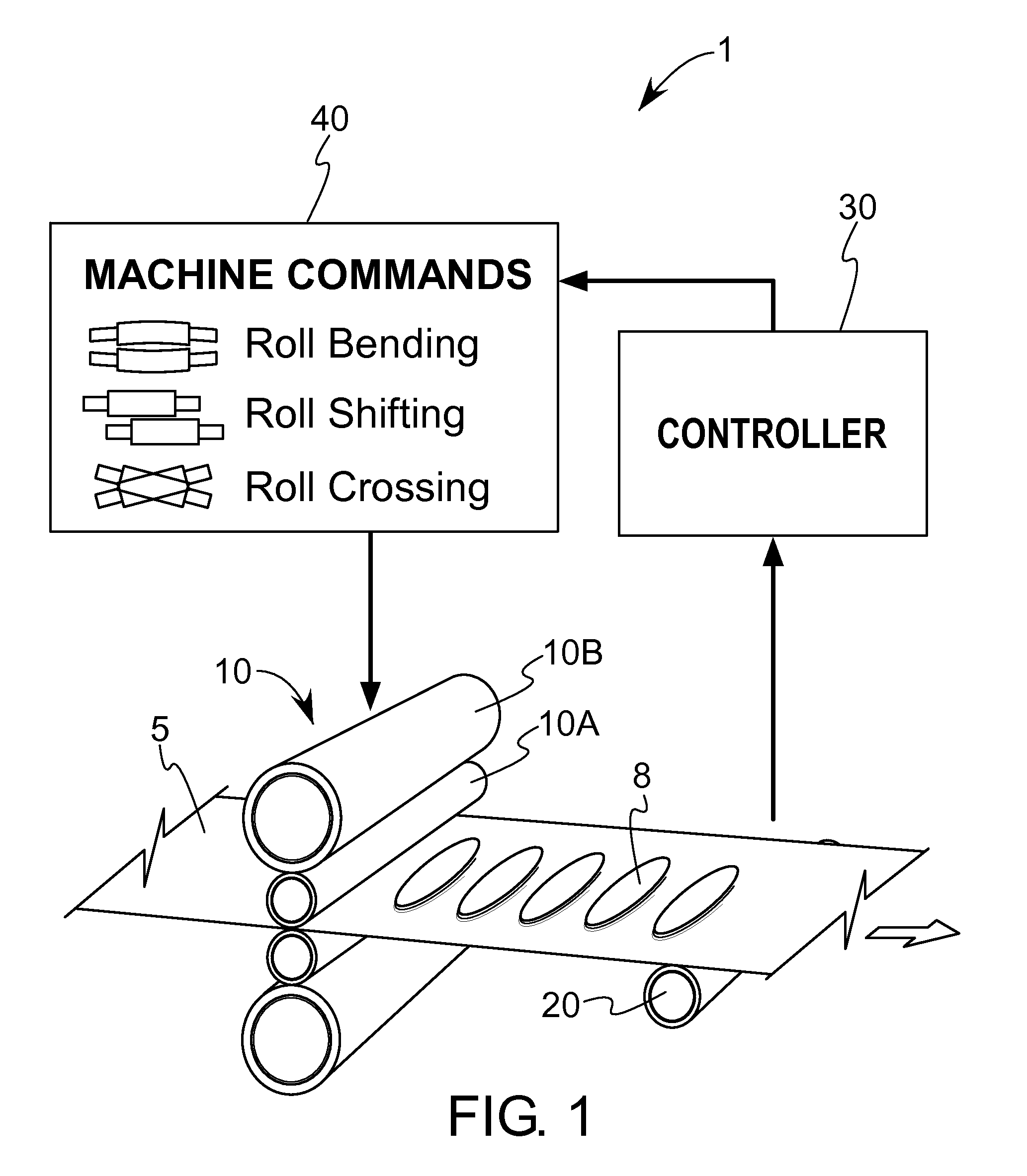
[0030]Referring first to FIG. 1, a simplified view of a system 1 to predict and control profile and flatness of strip 5 is shown. The system 1 includes a rolling mill made up of numerous rolls (also referred to as rollers) 10 configured to process strip 5 along rolling direction D which may alternate during successive reductions in thickness of strip 5. Other details of the rolling mill (including strip-conveying members in the form of feed and take-up reels, roll actuators, motors, drivers and related componentry for roll bending, crossing or shifting) are eliminated from the drawing to promote clarity. Rollers 10 may further be classified as work and backup rollers 10A and 10B, where the former contacts strip 5 and the latter contacts the former to provide backup. Flatness defects (or undulations) 8 that may be sensed and eventually corrected by system 1 are shown on strip 5 downstream of the rollers 10. The system 1 also includes one or more sensors 20 that may be located on eith...


PUM

PropertyMeasurementUnit
shapeaaaaaaaaaa
stiffnessaaaaaaaaaa
surface dimensionaaaaaaaaaa

Abstract

A device and method for prediction and / or control of the profile and / or shape of rolled metal strip. The device and method are compatible with both cluster-type and non cluster-type mills. The device and method employ a customized deflection model of the rolling mill, thereby combining the advantages of well-known finite element method with other relevant methods to allow real-time operation of the rolling mill without the computational complexities of such methods. In one form, the customized deflection model helps to obtain a compact, linear, and flexible analytical model with non-iterative solution, multiple continuous elastic foundations, third-order displacement fields, simple stress-field determination, and capability to compute dynamic deflection characteristics.

Description

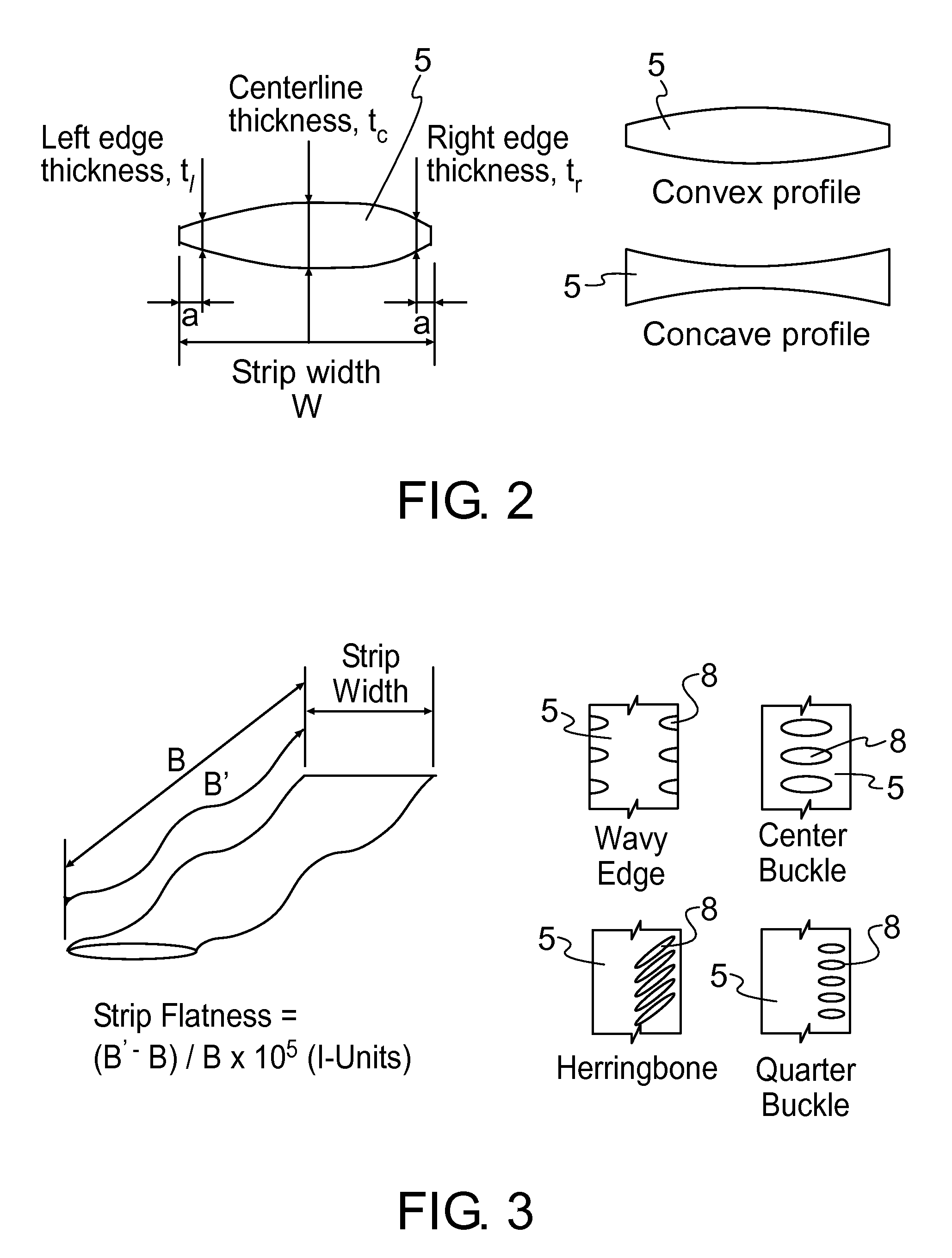
CROSS REFERENCE TO RELATED APPLICATION[0001]This application is a divisional of application Ser. No. 11 / 686,381 (now allowed), filed Mar. 15, 2007.BACKGROUND OF THE INVENTION[0002]The present invention generally relates to a device and method for improving the profile and flatness of a rolled article, and more particularly to a device and method that can calculate the cross-sectional thickness profile of the rolled article based on the machine parameters and provide instructions to control the article's profile and flatness accordingly. The invention even more particularly relates to predictive measurement and optional corrective actions by a controller on rolled metal plate, strip or sheet articles.[0003]Metal and non-metal articles in plate, strip or sheet form may be produced by rolling. The use of rolling equipment, especially rolling mills, is particularly prevalent in the production of metal articles. In order to achieve a high level of dimensional quality in the rolling of me...

Claims


Application Information

Patent Timeline
Patent Type & Authority Applications(United States)
IPC IPC(8): B21B37/24G06F19/00
CPCB21B37/28B21B37/38B21B37/40B21B2263/08B21B2263/02B21B2263/06B21B38/02
Inventor MALIK, ARIF S.GRANDHI, RAMANA V.
Owner WRIGHT STATE UNIVERSITY
Learn More