
Engine with gaseous and/or liquid fuel injector

a technology of liquid fuel injector and engine, which is applied in the direction of electrical control, process and machine control, instruments, etc., can solve the problems of increased risk of misfire, poor emissions, and significant time-consuming transition, so as to improve emissions, power, and power. the effect of improving efficiency

Active Publication Date: 2011-01-27
FORD GLOBAL TECH LLC
View PDF39 Cites 42 Cited by
  • Summary
  • Abstract
  • Description
  • Claims
  • Application Information

AI Technical Summary

Benefits of technology

Internal combustion engines can operate with more than one fuel type, such as gasoline and compressed natural gas (CNG), for example. A multi-fuel engine may take advantage of the properties of each fuel type to improve emissions, mileage, power, etc. A multi-fuel engine may also be less expensive to operate as the costs of different fuels vary over time.
One class of multi-fuel engines operating with liquid and gaseous fuels provides a separate set of injection hardware for each fuel. In this way, it is possible to provide accurate injection control for each fuel type, and easily handle transitions between the different fuel types.
One approach to address the above issues includes an engine mounted in a vehicle with a fuel delivery system delivering gaseous fuel and liquid fuel to a fuel injector of a cylinder, such that the fuel injector inlet faces at least partially toward the road surface. The orientation of the fuel injector enables a quick transition from liquid fuel to gaseous fuel because the gaseous fuel can rise to the injectors and be preferentially injected. For example, injection of gaseous fuel by the fuel injector may begin even before the fuel rail is entirely purged of liquid fuel. In this way, it is possible to transition fuels with a reduced set of fuel injection hardware, and further improve combustibility during the transition. As such, it can be possible to enable more transitions as the engine encounters varied operating conditions. This is especially true when the engine is mounted in a vehicle, as the engine may cycle through many operating conditions as the vehicle accelerates, decelerates, and encounters varied terrain.
In this way, it is possible to compensate for the transition of fuel types in the second injector by adjusting operation of the first injector. For example, when transitioning the second injector from liquid to gaseous fuel, the injection of the second injector may cease and the injection of the first injector may be increased such that the amount of power generated by the engine is maintained entering the transition. The fuel delivery system feeding the second injector is transitioned from liquid fuel to gaseous fuel by stopping delivery of liquid fuel, starting delivery of gaseous fuel, and purging the second injector of liquid fuel with small injections by the second injector. The transition completes by decreasing injection of the first injector, resuming injection on the second injector, and completely purging the fuel rail of liquid fuel using the high pressure gaseous fuel to push liquid fuel past a float valve and through a pressure relief valve in the liquid fuel system.

Problems solved by technology

However, the inventors herein have recognized that while transitions between the different fuel types is relatively simple due to the duplicative hardware set-up, the transition may take a significant amount of time to effect.
Other engines may operate during the transition, but may suffer from poor emissions and increased risk of misfire.
These difficulties may prevent the engine from taking full advantage of the properties of each fuel, since the cost of transitioning may exceed the savings of transitioning.

Method used


Image

  • Engine with gaseous and/or liquid fuel injector
  • Engine with gaseous and/or liquid fuel injector
  • Engine with gaseous and/or liquid fuel injector

Examples


Embodiment Construction

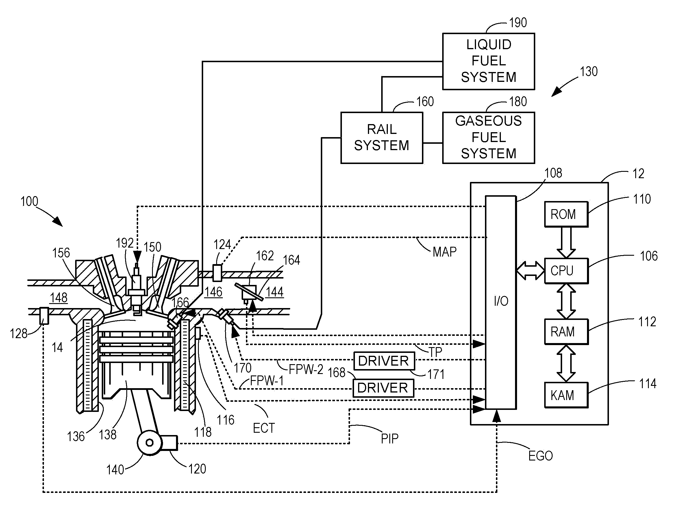
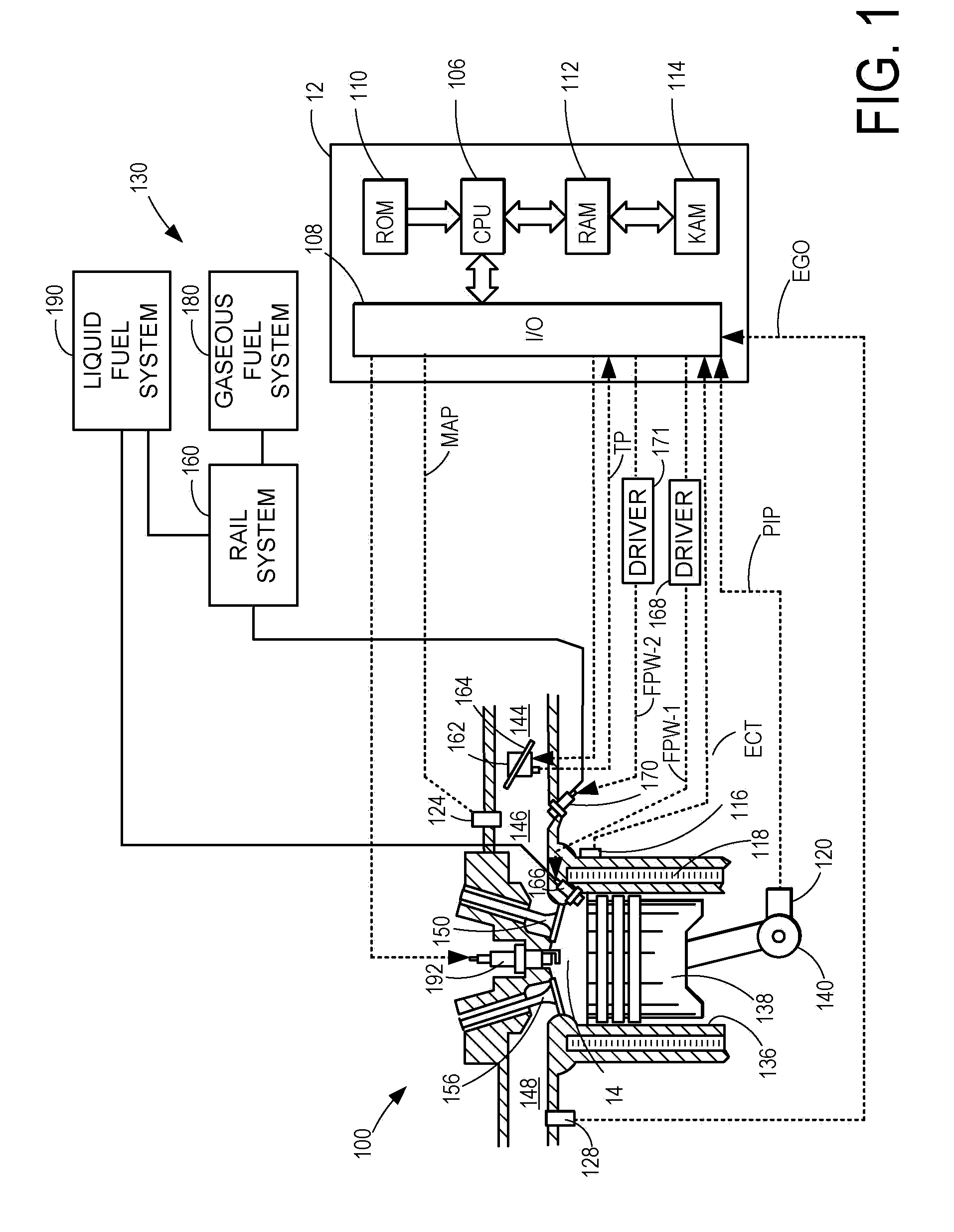
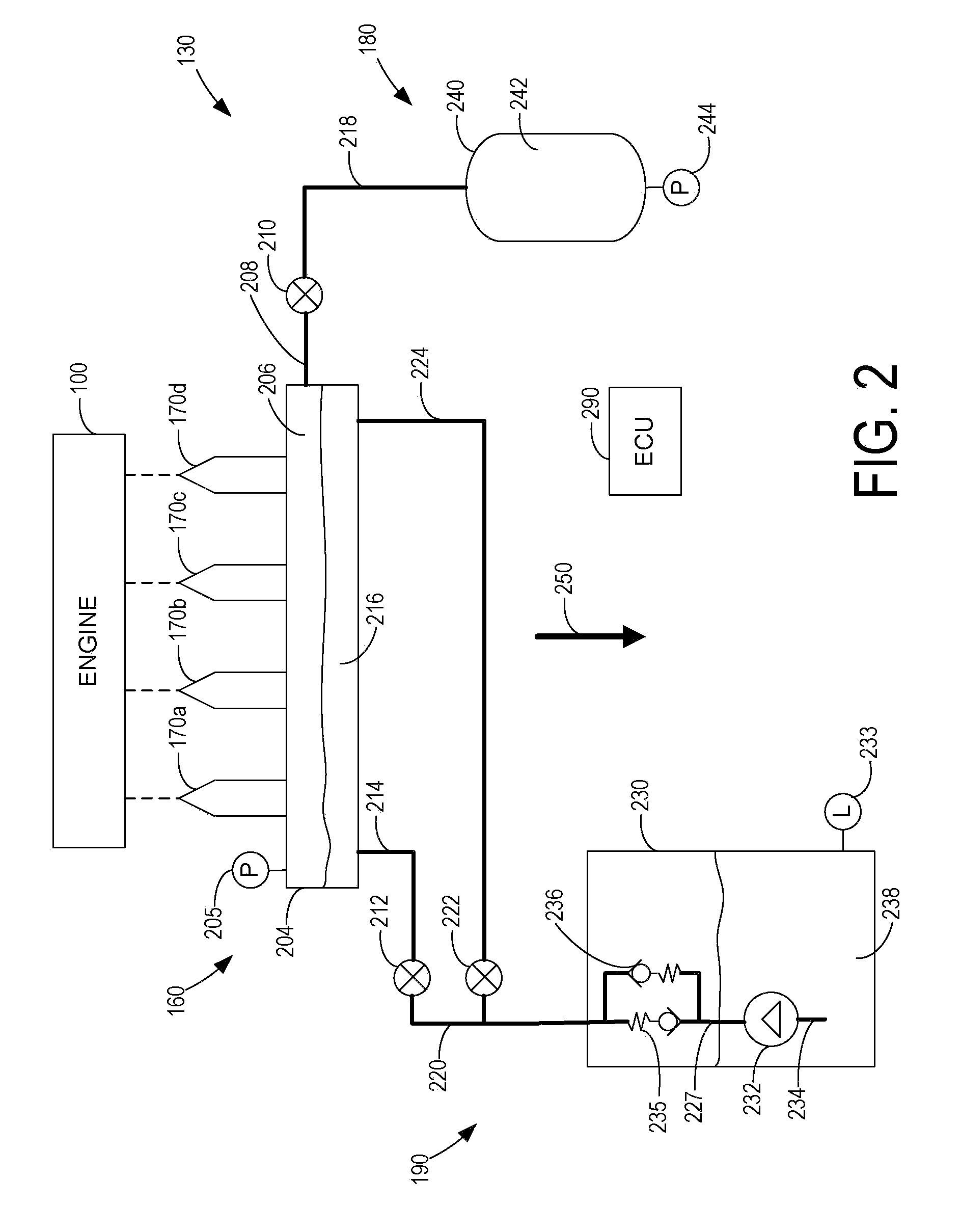
The following description relates to systems and methods for controlling an engine mounted in a vehicle travelling on a surface, the engine capable of operating with gaseous fuel and liquid fuel, injected separately and / or concurrently into the combustion chamber. For example, the engine (such as the one illustrated in FIG. 1) may include a first, direct, injector that directly injects liquid fuel into the combustion chamber and a second injector that injects fuel into the intake passage leading to the cylinder, where the intake nozzle of the second injector faces at least partially toward the surface. The gaseous and liquid fuel may be delivered by a fuel delivery system comprising a single fuel rail, such as illustrated in FIG. 2, or the fuel may be delivered by a fuel delivery system comprising a liquid fuel rail and a gaseous fuel rail as illustrated in FIG. 3. Further, the engine may include a control system with a routine to control the fuel delivery system such as illustrated...


PUM


Abstract

In one example, a system for a vehicle travelling on a surface is described. The system includes an engine with a cylinder. The cylinder includes a fuel injector that is supplied with gaseous fuel and liquid fuel by a fuel delivery system. The fuel injector is mounted in the vehicle such that the fuel injector inlet faces at least partially toward the road surface. The orientation of the fuel injector enables a quick transition from liquid fuel to gaseous fuel because the gaseous fuel can rise to the injectors and be preferentially injected. Further, various approaches are described from transitioning operation between gaseous and liquid fuel injection.

Description

FIELDThe present application relates to methods and apparatus for delivering gaseous and / or liquid fuels to a fuel injection system of an internal combustion engine.BACKGROUND AND SUMMARYInternal combustion engines can operate with more than one fuel type, such as gasoline and compressed natural gas (CNG), for example. A multi-fuel engine may take advantage of the properties of each fuel type to improve emissions, mileage, power, etc. A multi-fuel engine may also be less expensive to operate as the costs of different fuels vary over time.One class of multi-fuel engines operating with liquid and gaseous fuels provides a separate set of injection hardware for each fuel. In this way, it is possible to provide accurate injection control for each fuel type, and easily handle transitions between the different fuel types.However, the inventors herein have recognized that while transitions between the different fuel types is relatively simple due to the duplicative hardware set-up, the tran...

Claims


Application Information

Patent Timeline
Patent Type & Authority Applications(United States)
IPC IPC(8): F02M43/00F02M69/46F02D41/30
CPCF02B2075/125F02D19/0694F02D19/0628F02D19/0647F02D19/081F02D41/0025F02D41/3064F02D41/3094F02D2200/0602Y02T10/36F02D19/0697Y02T10/123F02D19/061F02D19/0689F02D19/0692F02B2275/16Y02T10/12Y02T10/30
Inventor ULREY, JOSEPH NORMANPURSIFULL, ROSS DYKSTRA
Owner FORD GLOBAL TECH LLC
Learn More