
Delivery module for selective catalytic reduction

a delivery module and catalytic reduction technology, applied in the direction of machines/engines, combustion types, lighting and heating apparatuses, etc., can solve the problems of adverse effect on cost and space, high cost, and large space requirements of the first sketched version of the common housing, and achieve the effect of high degree of design freedom

Active Publication Date: 2011-01-27
ROBERT BOSCH GMBH
View PDF6 Cites 10 Cited by
  • Summary
  • Abstract
  • Description
  • Claims
  • Application Information

AI Technical Summary

Benefits of technology

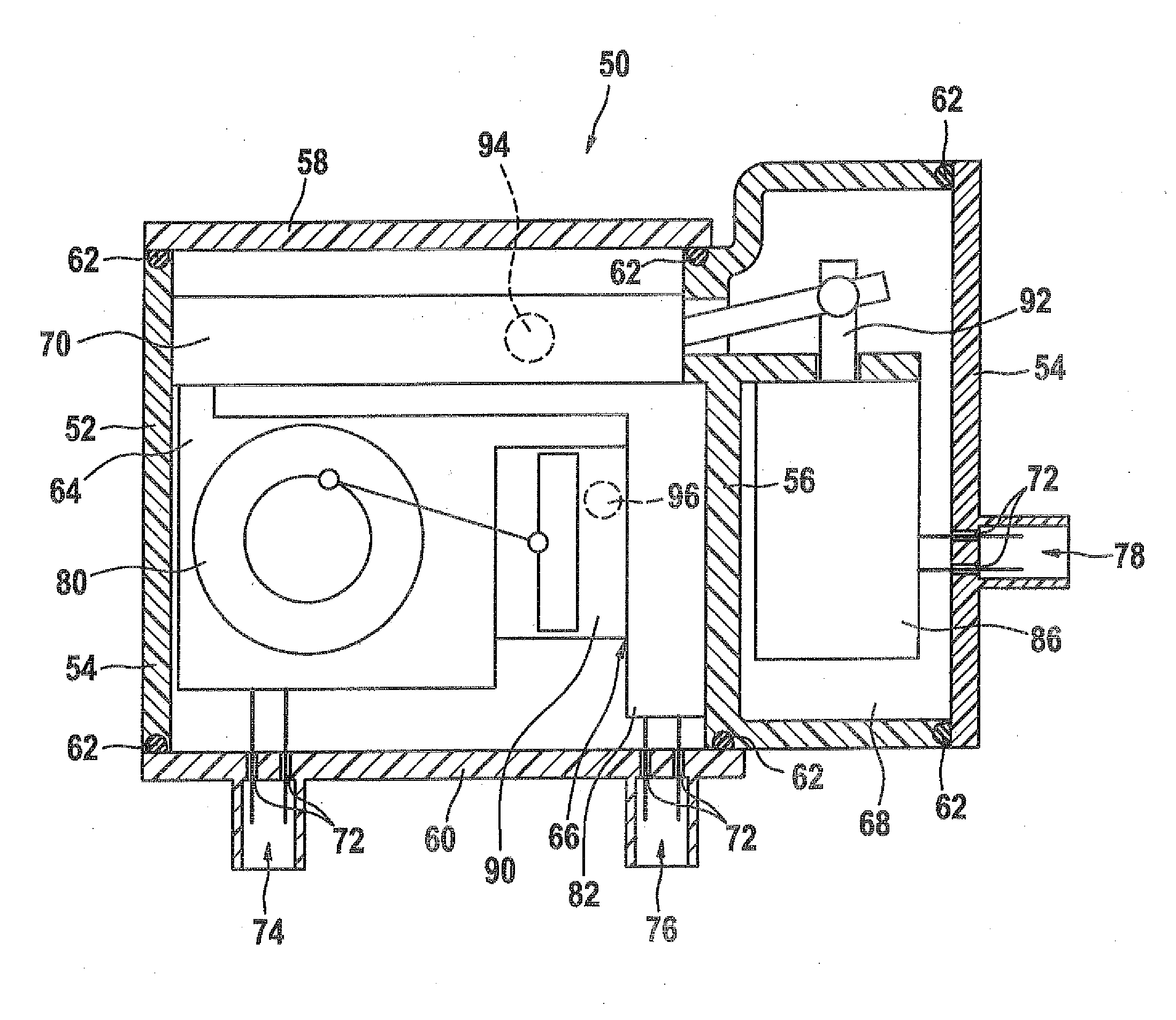
[0004]According to the invention, it is proposed that a component of the metering system for introducing a reducing agent into the exhaust gas of an internal combustion engine be embodied as a primary component in such a way that further components can be integrated with the selected primary component in drawerlike or modular fashion, so that a compact complete unit is obtained. In practice, a reversing valve, for instance, which may for instance be a 4 / 2-way valve, can be selected as the primary component, in the housing of which drawerlike compartments or drawerlike chambers for the other components, such as a delivery module of the metering system, can be embodied for introducing a reducing agent into the exhaust gas of an internal combustion engine. According to the invention, it is proposed that the housing of the selected primary component be provided with a plurality of drawers. Since the housing of the primary component is fabricated economically, offering a high degree of design freedom, in the course of the plastic injection molding process, the chambers required for the drawers can be made relatively simply from plastic. Further components, such as a pressure sensor and at least one filter on the compression side, can easily be inserted into these drawers in the housing of the primary component. Once the applicable component has been built into the particular drawer provided for it in the housing of the primary component, individual chambers can be closed via separate plastic lids. The closure of the individual chambers via separate plastic lids can be done for instance by way of securing a lid to the drawer by means of a clip connection or screw connection or by embodying material-locking connection, for instance in the course of the plastic friction welding.
[0006]Advantageously, a heater can be injection-molded into the housing of the primary component, which housing is preferably made in the course of the plastic injection molding process and in which the various chambers are embodied for receiving the drawers and components. If this heater is injection-molded directly into the plastic housing, then in contrast to a screwed-on heater, which is in contact at most at one point and thus can transmit heat via this one side in the course of the heat conduction, considerably better heat input into the drawers accommodated in the housing of the primary components, or in other words into the components integrated with these drawers, can be achieved.

Problems solved by technology

Because of the hydraulic communication of the components with one another via hoses and because of the electrical triggering of the individual components with a central plug via a cable harness, the common housing in the first version sketched at the outset is extremely expensive and requires an extremely large amount of space.
In addition to the components accommodated in a common housing, the hydraulic lines also each require heaters, which have an adverse effect on cost and space and in an individual case must be procured from the automobile manufacturer with regard to the required specifications.
This can be extremely complicated, since in the SCR process, some of the components are actuated via levers, as in the case of the reversing valve for the pump, or an eccentric drive mechanism by an actuation magnet or an electric drive mechanism.
This makes separate sealing for each component, as is known in the second embodiment previously chosen and known from the prior art, extremely difficult.
Moreover, heating the components of an SCR system that are accommodated outside a common mounting block and received there proves extremely difficult, especially with regard to heat transfer from a heat source to the individual components received on a common mounting block.

Method used


Image

  • Delivery module for selective catalytic reduction
  • Delivery module for selective catalytic reduction
  • Delivery module for selective catalytic reduction

Examples


Embodiment Construction

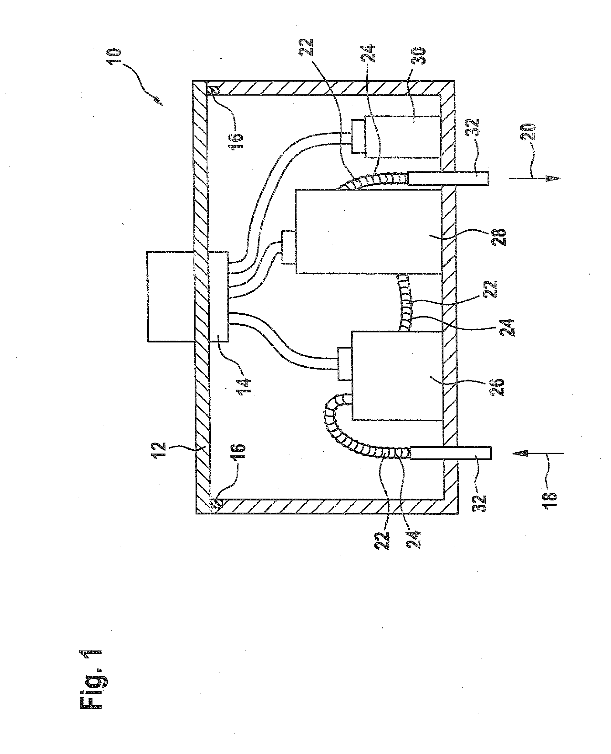
[0012]In FIG. 1, a first embodiment of a delivery module according to the prior art can be seen in which the components of a delivery module of a metering system are integrated with a common housing that is sealed off from the outside.

[0013]It can be seen from FIG. 1 that a plurality of components 26, 28, 30 of a delivery module for delivering a reducing agent inside a metering system are disposed inside a central housing 10. In FIG. 1, the first component 26, second component 28, and third component 30 are secured to the bottom of the central housing 10. The central housing 10 is closed by a lid 12, which is sealed off by means of a sealing ring 16 extending all the way around. A central plug with a cable harness 14 is integrated with the lid 12, and by way of it the individual components 26, 28, 30 are electrically contacted inside the central housing 10. An inlet 18 extends into the central housing 10 through its bottom, and the reducing agent leaves the central housing 10 via a ...


PUM


Abstract

The invention relates to a delivery module for a dosage system used to introduce a reducing agent into the exhaust gas tract of an internal combustion engine. The delivery module has a housing, which accommodates various components, and which is produced as an injection moulded component. A heating system is integrated in the vicinity of the center of the housing. The housing has at least one chamber for receiving additional components.

Description

PRIOR ART[0001]In motor vehicles with internal combustion engines, because of the increasingly stringent laws regarding exhaust gases expected in the next few years, the pollutant NOx contained in the exhaust gas of internal combustion engines must be reduced. One currently used method for this is the SCR process (Selective Catalytic Reduction), in which the pollutant NOx is reduced to N2 or H2O, using liquid reducing agent. The reducing agent used, as a rule in liquid form, is received in a tank and is fed by a delivery module from the tank via a line to a metering module for injecting the reducing agent into the exhaust gas. The goal is to position the metering system, with its components, that is, tank delivery module lines, metering module, and the like, outside the passenger compartment of the motor vehicle, since at elevated temperatures, ammonia (NH3) forms from the aqueous urea solution used as the reducing agent. With this concept of accommodating the entire metering system...

Claims


Application Information

Patent Timeline
IPC IPC(8): F01N3/20
CPCF01N3/2066F01N2240/16F01N2610/02Y02T10/24F01N2610/14F01N2610/1433F01N2610/10Y02T10/12
Inventor HAEBERER, RAINERHORN, MATTHIAS
Owner ROBERT BOSCH GMBH
Learn More