
Method for forming carbon nanotube film, film-forming apparatus, and carbon nanotube film

a technology of carbon nanotubes and film-forming equipment, which is applied in the direction of chemical apparatus and processes, synthetic resin layered products, coatings, etc., can solve the problems of impairment of electrical conductivity due to nonconductive organic substances adhering to the surface of cnts, polymeric and non-heat-resistant inorganic substrates cannot be used, and achieve efficient mass-producing cnt films. , the effect of low cos

Inactive Publication Date: 2011-01-20
NAT INST OF ADVANCED IND SCI & TECH
View PDF5 Cites 27 Cited by
  • Summary
  • Abstract
  • Description
  • Claims
  • Application Information

AI Technical Summary

Benefits of technology

[0030]The method and apparatus for forming a CNT film of the present invention can efficiently mass-produce the CNT film at low cost.
[0031]In addition, since the method and apparatus for forming a CNT film of the present invention do not require any dispersion process, a reproducible film-forming technology can be realized.
[0032]Furthermore, the method and apparatus for forming a CNT film of the present invention employ a dry process, which is particularly suitable for electronic devices.
[0033]Moreover, with the method and the apparatus for forming a CNT film of the present invention, a CNT film is obtained by uniformly depositing CNTs. The CNT film has homogeneous semiconductive, mechanical and optical characteristics. Accordingly, the present invention provides a significant industrial contribution to the electronic field.

Problems solved by technology

Since the dispersion of CNTs is difficult to achieve, it is challenging to establish a reproducible film-forming technology.
Even for the method disclosed in Patent Document 1, in which the CNTs are uniformly dispersed, the problem of impairment in electrical conductivity due to nonconductive organic substances adhering to the surface of the CNTs remains.
On the other hand, even if the dry process is used in the method disclosed in Non-patent Document 5, the following problem remains.
Since the reaction temperature for the formation of the SWCNTs is generally equal to or higher than 500° C., only highly heat-resistant substrates are applicable, while polymeric and non-heat-resistant inorganic substrates cannot be used.

Method used


Image

  • Method for forming carbon nanotube film, film-forming apparatus, and carbon nanotube film
  • Method for forming carbon nanotube film, film-forming apparatus, and carbon nanotube film
  • Method for forming carbon nanotube film, film-forming apparatus, and carbon nanotube film

Examples


embodiments

[0089]Embodiments of the present invention are illustrated below with reference to the accompanying drawings. In addition, the following embodiments are provided in order for the present invention to be comprehensible, and are not intended to limit the present invention. It is understood that variations, embodiments and other examples made based on the technical ideas of the present invention should also fall within the scope of the present invention.

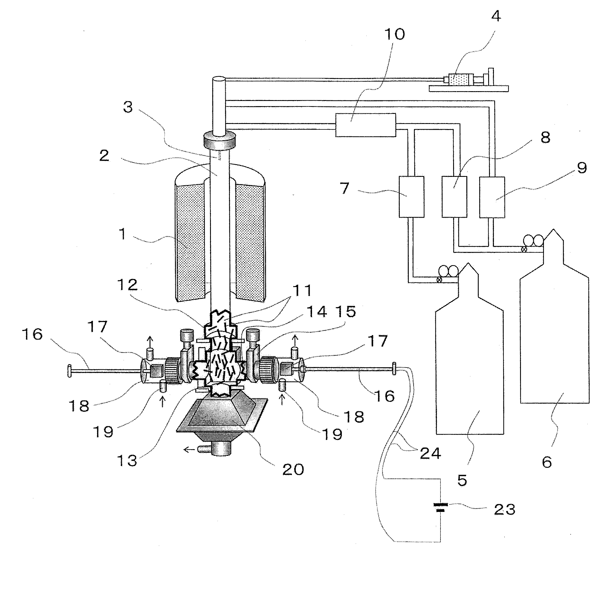
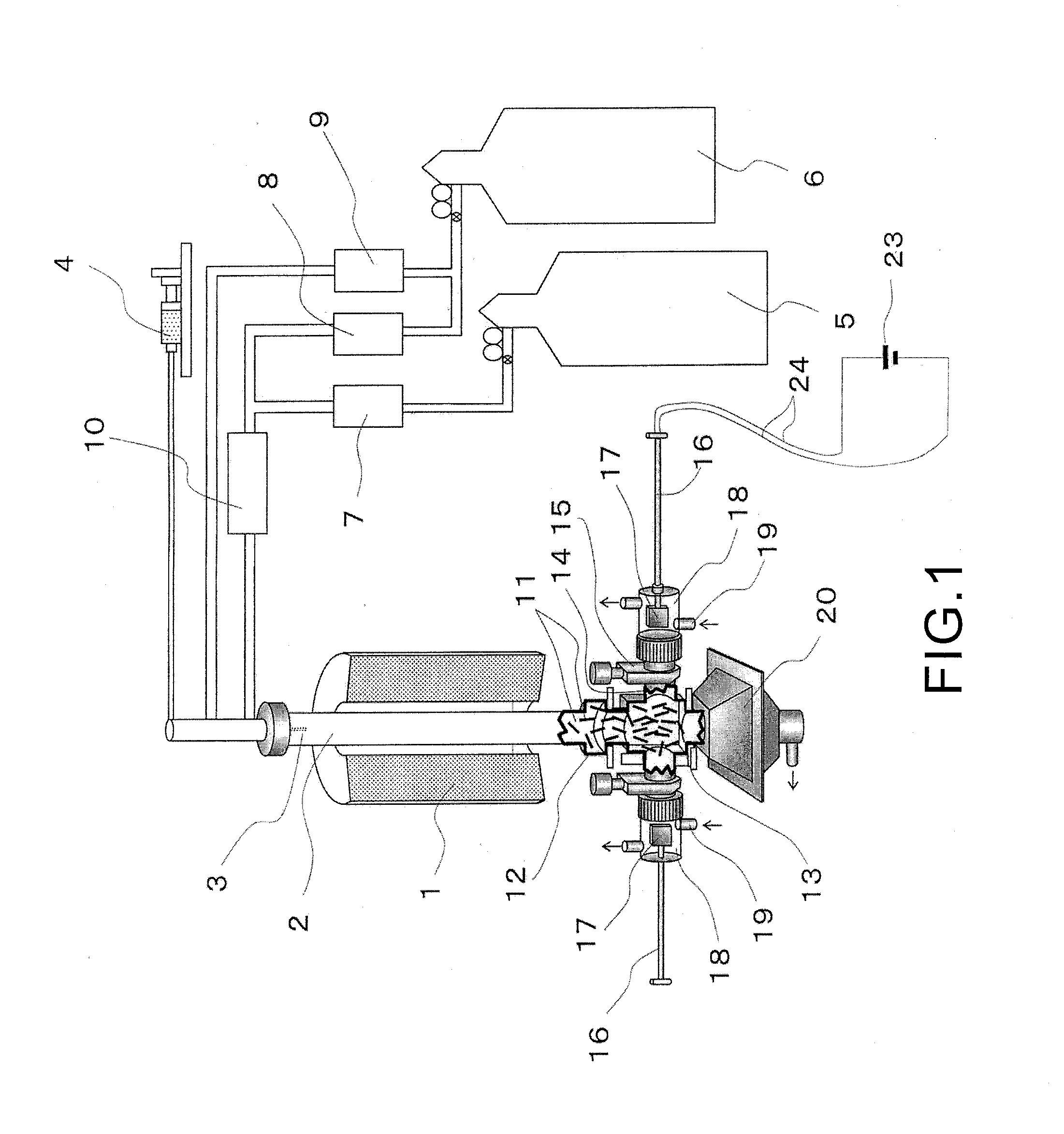
[0090]FIG. 1 is a front view of an apparatus for forming a SWCNT film according to an embodiment of the present invention, the essential parts of the apparatus are shown in a cross section.

[0091]The part in the apparatus for synthesizing SWCNTs 11 includes an electric furnace 1, a mullite reaction tube 2, a spray nozzle 3, a microfeeder 4, a second carbon source 5, a carrier gas source 6, a mass flow controller of the second carbon source 7, a mass flow controller of the first carrier gas 8, a mass flow controller of the second carrier ...


PUM

PropertyMeasurementUnit
Temperatureaaaaaaaaaa

Abstract

A method and an apparatus for efficiently mass-producing a single-wall carbon nanotube (SWCNT) film are disclosed. The SWCNT film is useful as an industrial material, at low temperature and low cost. The method and apparatus are characterized in that carbon nano-tubes (CNTs) are synthesized from a raw material source through a gas-phase chemical vapor deposition (CVD) process, and the synthesized CNTs are directly deposited on a substrate in a chamber connected with a reaction tube, thereby forming a CNT film on the substrate.

Description

BACKGROUND OF THE INVENTION[0001]1. Field of the Invention[0002]The present invention generally relates to a method and an apparatus for forming a carbon nanotube (CNT) film containing single-wall carbon nanotubes (SWCNTs), and a CNT film, in particular, to a method and an apparatus for mass-producing a carbon nanotube (CNT) film from a raw material source at a low temperature of 200° C. or less at low cost through a gas-phase chemical vapor deposition (CVD) process, and a film.[0003]2. Description of Related Art[0004]A nanotube is a tube-shaped molecule formed by a network of chemical bonds, and a typical nanotube is a CNT in a tube-shaped network structure formed of graphite carbon. The CNT produced for the first time in 1991 was a multiwall carbon nanotube (MWCNT), and a single-wall carbon nanotube (SWCNT) was produced in 1993. Thereafter, the discovery of BNC nanotubes and BN nanotubes, in which boron (B) or nitride (N) was substituted for a portion or all of carbon atoms, was a...

Claims


Application Information

Patent Timeline
IPC IPC(8): C23C16/26
CPCB82Y30/00C01B31/024B82Y40/00C01B32/164
Inventor SAITO, TAKESHI
Owner NAT INST OF ADVANCED IND SCI & TECH
Learn More