
Tft. shift register, scan signal line driving circuit, display device, and TFT trimming method

a shift register and scan signal technology, applied in the field of tft, can solve the problems of reducing the proportion of non-defective panels obtained in the manufacture of tfts with low yield, affecting the normal operation of the entire tft, and the probability of leakage between two opposing electrodes of the bootstrap capacitor, etc., to achieve the effect of reducing the proportion of non-defective panels, low yield, and wide channel width

Inactive Publication Date: 2011-01-20
SHARP KK
View PDF13 Cites 39 Cited by
  • Summary
  • Abstract
  • Description
  • Claims
  • Application Information

AI Technical Summary

Benefits of technology

[0015]Such a large area occupied by the bootstrap capacitor results in a higher probability of the occurrence of leakage between two opposed electrodes of the bootstrap capacitor. If the bootstrap capacitor has leakage in at least one spot, the entire TFT fails to operate normally. This decreases manufacturing yield of TFTs and, in turn, seriously decreases manufacturing yield of display panels.
[0085]The above invention produces the, effect of realizing a display device which can be easily saved from being a defective product even if leakage occurs in the capacitor connected to the TFT body section.

Problems solved by technology

Therefore, it is inevitable that manufacturing of TFTs with low yield seriously decreases a proportion of non-defective panels obtained.
Such a large area occupied by the bootstrap capacitor results in a higher probability of the occurrence of leakage between two opposed electrodes of the bootstrap capacitor.
If the bootstrap capacitor has leakage in at least one spot, the entire TFT fails to operate normally.
This decreases manufacturing yield of TFTs and, in turn, seriously decreases manufacturing yield of display panels.
Thus, the conventional TFT provided with a bootstrap capacitor has the problem that it is liable to have lower manufacturing yield due to the occurrence of leakage in the bootstrap capacitor.

Method used


Image

  • Tft. shift register, scan signal line driving circuit, display device, and TFT trimming method
  • Tft. shift register, scan signal line driving circuit, display device, and TFT trimming method
  • Tft. shift register, scan signal line driving circuit, display device, and TFT trimming method

Examples


example 1

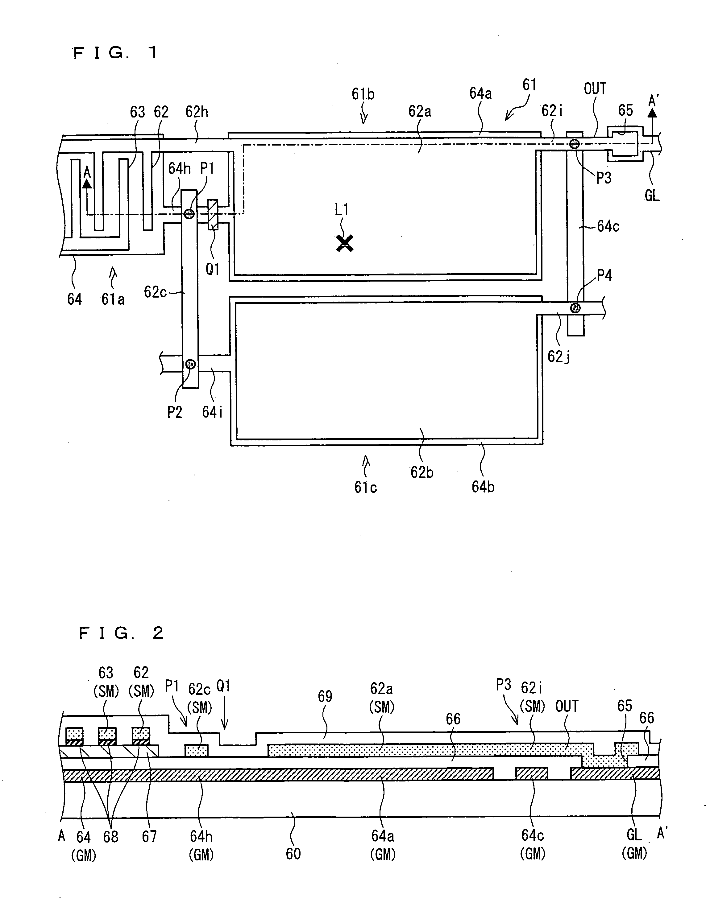
[0189]The following will describe a TFT of the present example with reference to FIGS. 1 and 2.

[0190]FIG. 1 shows a plan view of the structure of a TFT 61 applicable to the transistor Tr4 and provided on the display panel 2, according to the present example.

[0191]The TFT 61 includes a TFT body section 61a, capacitors 61b and 61c, and interconnections 62c and 64c. Each of the capacitors 61b and 61c is a capacitor capable of serving as a bootstrap capacitor and applicable to the capacitor CAP.

[0192]The TFT body section 61a has a comb-shaped source electrode 62 and a comb-shaped drain electrode 63 disposed above a gate electrode 64 in a thickness direction and opposed to each other in a panel plane in such a manner that the source electrode 62 and drain electrode 63 are engaged with each other, which secures a large channel width. However, this is merely one arrangement example. The source electrode 62, the drain electrode 63, and the gate electrode 64 may be disposed at any positions ...

example 2

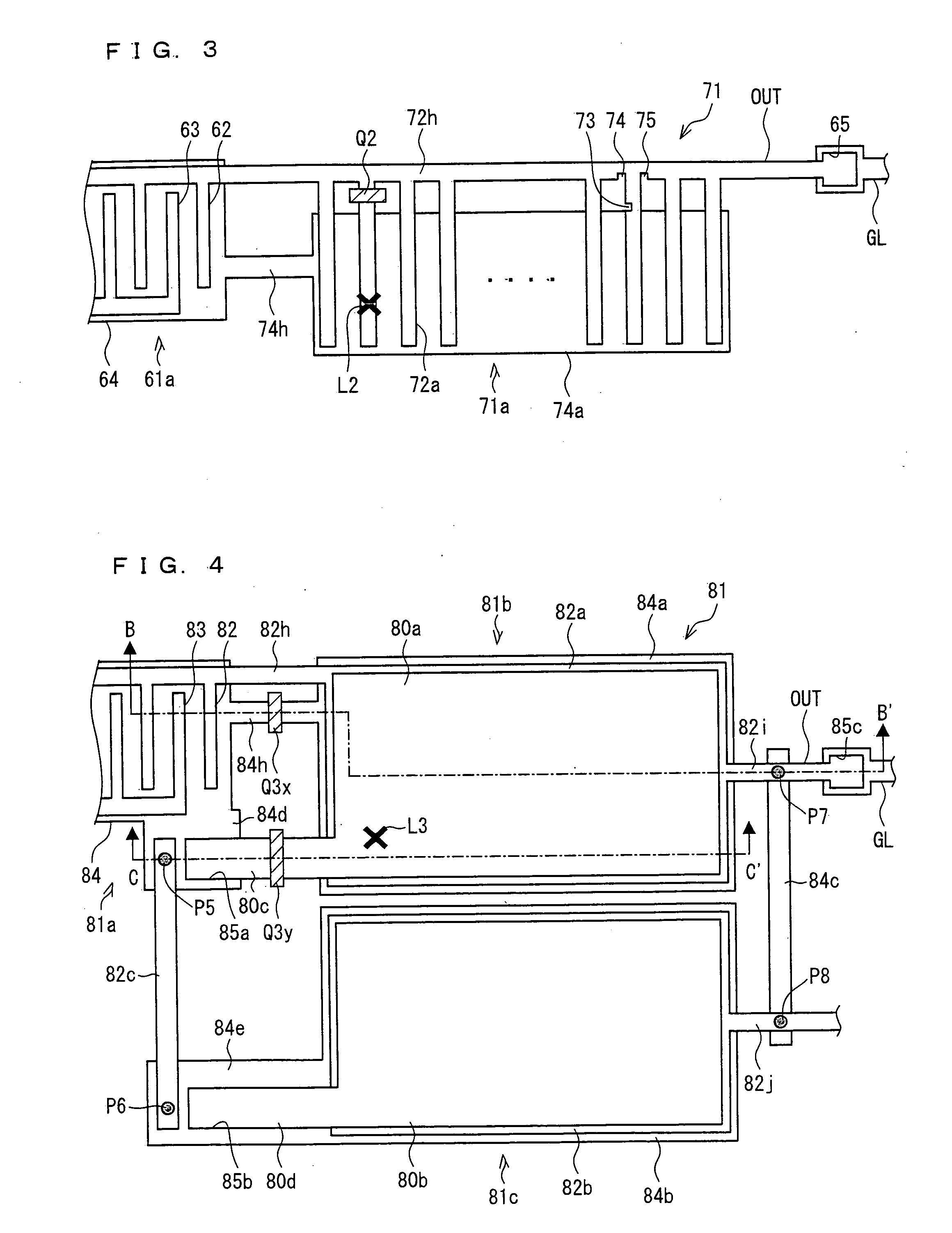
[0206]A TFT of the present example will be described with reference to FIG. 3. Unless otherwise noted, members given the same reference numerals as those shown in FIGS. 1 and 2 have the same functions as the members in FIGS. 1 and 2.

[0207]FIG. 3 shows a plan view of the structure of a TFT 71 applicable to the transistor Tr4 and provided on the display panel 2, according to the present example.

[0208]The TFT 71 includes a TFT body section 61a, a capacitor 71a, and interconnections 72h and 74h. The capacitor 71a is a capacitor capable of serving as a bootstrap capacitor and applicable to the capacitor CAP.

[0209]The capacitor 71a is formed so as to have a region where a plurality of first capacitor electrodes 72a and a second capacitor electrode 74a are arranged to be stacked in the thickness direction and mutually opposed across a gate dielectric layer 66 therebetween. The plurality of first capacitor electrodes 72a are formed so as to be led out from the lead-out line 72h, which is le...

example 3

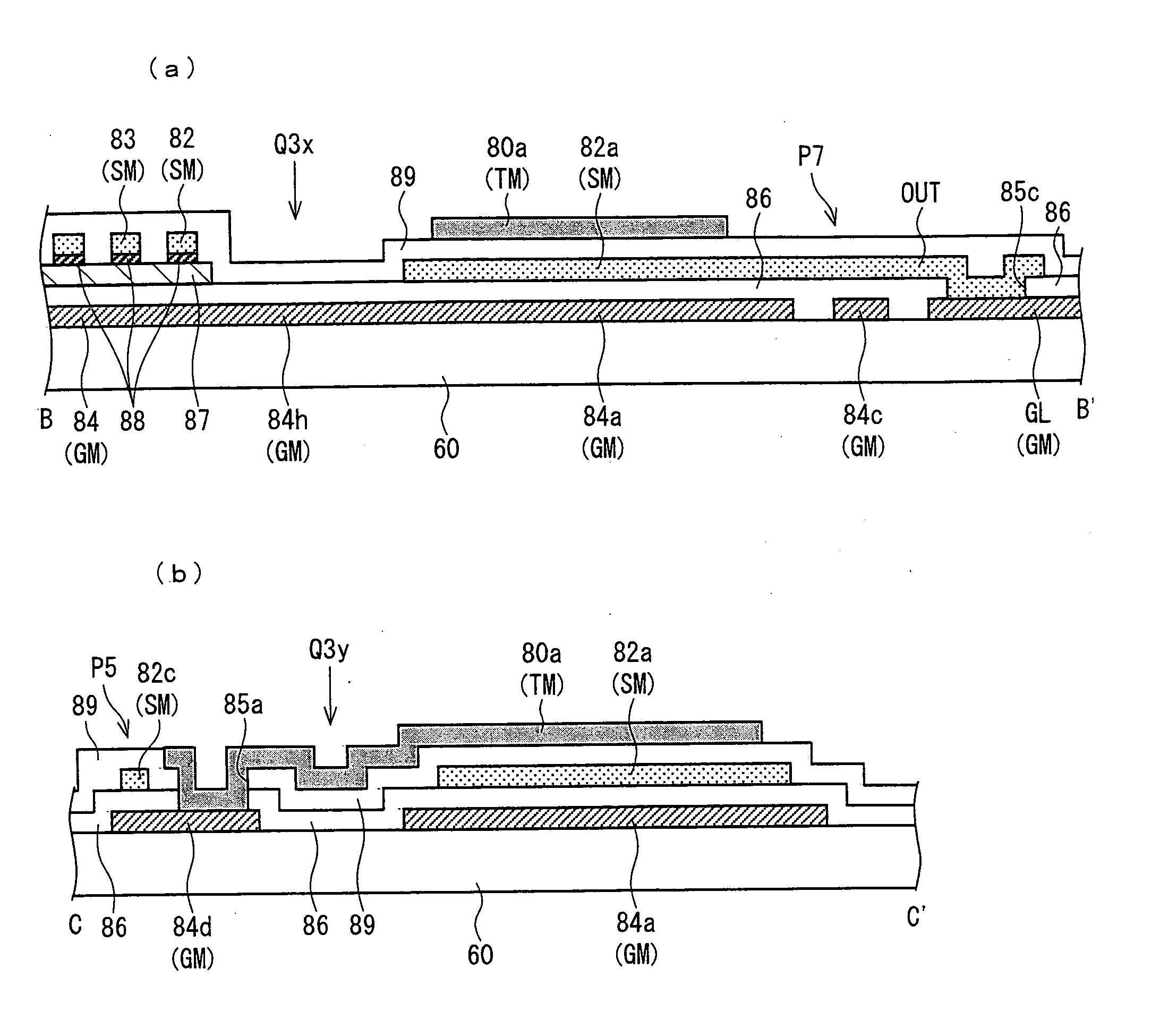
[0216]The following will describe a TFT of the present example with reference to FIGS. 4 and 5.

[0217]FIG. 4 shows a plan view of the structure of a TFT 81 applicable to the transistor Tr4 and provided on the display panel 2, according to the present example.

[0218]The TFT 81 includes a TFT body section 81a, capacitors 81b and 81c, and interconnections 82c and 84c. Each of the capacitors 81b and 81c is a capacitor capable of serving as a bootstrap capacitor and applicable to the capacitor CAP.

[0219]The TFT body section 81a has a comb-shaped source electrode 82 and a comb-shaped drain electrode 83 disposed above a gate electrode 84 in a thickness direction, and opposed to each other in a panel plane in such a manner that the source electrode 82 and drain electrode 83 are engaged with each other, which secures a large channel width. However, this is merely one arrangement example. The source electrode 82, the drain electrode 83, and the gate electrode 84 may be disposed at any positions...


PUM


Abstract

In at least one embodiment, a TFT includes: a first capacitor formed of a first capacitor electrode connected to a source electrode and a second capacitor electrode; a second capacitor formed of a third capacitor electrode and a fourth capacitor electrode; a first lead-out line; a second lead-out line connected to a gate electrode; a third lead-out line; a fourth lead-out line; a first interconnection; and a second interconnection. This realizes a TFT which can be easily saved from being a defective product even if leakage occurs in a capacitor connected to a TFT body section.

Description

TECHNICAL FIELD[0001]The present invention relates to a TFT including a capacitor that is added between a gate and a source.BACKGROUND ART[0002]In recent years, monolithic integration of a gate driver has been developed for the purpose of cost reduction. In the monolithic integration, the gate driver is formed from amorphous silicon on a liquid crystal panel. The term “monolitic gate driver” is also associated with the terms such as “gate driver-free”, “built-in gate driver in panel”, and “gate in panel”. For example, Patent Literature 1 discloses shift registers of monolithic gate drivers.[0003]FIG. 11 shows circuit configuration of each shift register stage disclosed in Patent Literature 1.The fo11owing describes essential structure and operations of this circuit. FIG. 11 shows the structure of an n-th stage of shift register stages cascaded with each other. To an input terminal 12, a gate output from a preceding stage is supplied. This supply causes an output transistor 16 to be ...

Claims


Application Information

Patent Timeline
Patent Type & Authority Applications(United States)
IPC IPC(8): G06F3/038H01L29/94H01L21/326G11C19/00
CPCG09G3/3677H01L28/86H01L27/1255H01L27/13H01L27/12H01L27/1214H01L27/124
Inventor TANAKA, SHINYAKIKUCHI, TETSUOIMAI, HAJIMEKITAGAWA, HIDEKIKATAOKA, YOSHIHARU
Owner SHARP KK
Learn More