Catalyst assembly for use in anode gas oxidizing systems of high temperature fuel cells

a catalyst and gas oxidizing system technology, applied in the direction of physical/chemical process catalysts, cell components, separation processes, etc., can solve the problems of increasing the difference between the cathode inlet stream, increasing the pressure of the anode exhaust stream, and increasing the temperature distribution from one end of the assembly, so as to reduce increase the density of the channel, and increase the width of the channel

Active Publication Date: 2010-03-16
FUELCELL ENERGY INC
View PDF10 Cites 0 Cited by
  • Summary
  • Abstract
  • Description
  • Claims
  • Application Information

AI Technical Summary

Benefits of technology

[0010]In accordance with the principles of the present invention, the above and other objectives are realized in an oxidizer catalyst assembly for use in a fuel cell system for oxidizing anode exhaust gas in which a first catalyst member is arranged along a gas flow path and is followed by a second catalyst member also arranged along the gas flow path. Each of the first and second catalyst members includes a plurality of through channels for passing gas therethrough and an oxidizing catalyst deposited in the channels. The first and second catalyst members are further configured such that the channel density and the channel width of the channels of the first catalyst member are less than and greater than, respectively, the channel density and the channel width of the channels of the second catalyst member. In this way, any clogging of the catalyst assembly at the first catalyst member is avoided due to the decreased channel density and larger channel width of the first catalyst member channels, while a catalyst activity sufficient to realize a desired oxidation is obtained due to the increased channel density and decreased channel width of the second catalyst member channels.

Problems solved by technology

The electrolyte particulate deposits create a partial obstruction of the flow path of the gas mixture into and through the oxidizer catalyst, resulting in an increased build-up of pressure across the catalyst assembly and thus increasing the difference between the pressure of the anode exhaust stream and the cathode inlet stream.
In addition, the blockage by the electrolyte deposits changes the flow distribution through the catalyst assembly, resulting in a larger difference in temperature distribution from one end of the assembly to the other.
Particularly, the increasing pressure difference between the anode and the cathode streams due to the aforementioned accumulation of electrolyte particulate deposits on the oxidizer catalyst assembly affects the thermal profile and voltage variations of the fuel cell stack.
Moreover, electrolyte particulate deposits may deactivate the oxidizer catalyst which affects its hydrocarbon oxidation efficiency.
However, even the in-situ removal methods described in the '914 application usually require the fuel cell plant to be temporarily taken off-line, thus interrupting power generation and delivery.

Method used


Image

  • Catalyst assembly for use in anode gas oxidizing systems of high temperature fuel cells
  • Catalyst assembly for use in anode gas oxidizing systems of high temperature fuel cells
  • Catalyst assembly for use in anode gas oxidizing systems of high temperature fuel cells

Examples


Embodiment Construction

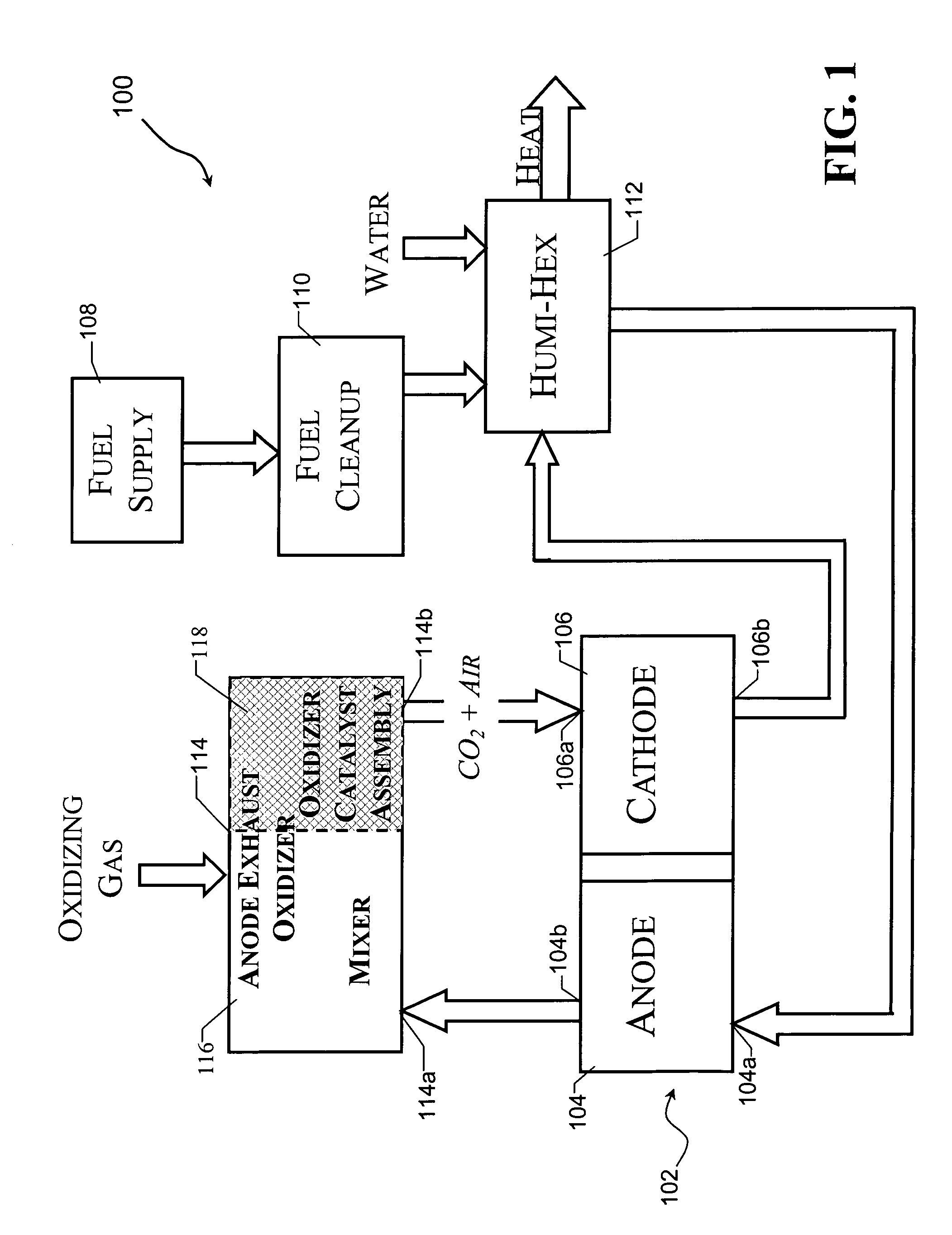
[0019]FIG. 1 shows a schematic view of a fuel cell system 100 which is adapted to use an oxidizer catalyst assembly 118 in accordance with the principles of the present invention. The fuel cell system includes a fuel cell 102 having an anode 104 and a cathode 106. Fuel gas, such as natural gas, is supplied to the system 100 from a fuel supply 108. Before being conveyed to the anode 104, the fuel undergoes fuel cleanup processing at the fuel cleanup stage 110, and is combined with water and heated in a heat exchanger 112. Processed heated fuel enters the anode 104 through an anode inlet 104a to undergo an electrochemical reaction. Spent fuel leaves the anode 104 through an anode outlet 104b as the anode exhaust gas.

[0020]In the illustrative case shown, the oxidizer catalyst assembly 118 is included in an anode exhaust gas oxidizer 114 whose inlet 114a is coupled to the outlet 104b of the anode 104. The anode exhaust gas oxidizer 114 also includes a mixer 116 which receives the anode ...


PUM

PropertyMeasurementUnit
distanceaaaaaaaaaa
distanceaaaaaaaaaa
widthaaaaaaaaaa

Abstract

An oxidizer catalyst assembly for use in a fuel cell system for oxidizing anode exhaust gas and in which a first catalyst member is situated along a gas flow path and a second catalyst member is situated along the gas flow path following the first catalyst member. Each of the catalyst members includes a plurality of channels for passing the gas therethrough and an oxidizing catalyst deposited in the channels. The channel density of the channels of the second catalyst member is greater than the channel density of the channels of the first catalyst member and the channel width of the channels of the second catalyst member is less than the channel width of the channels of the first catalyst member.

Description

BACKGROUND OF THE INVENTION[0001]This invention relates to fuel cell systems and, in particular, to a catalyst assembly for use in gas oxidizers used in such systems.[0002]A fuel cell is a device which directly converts chemical energy stored in hydrocarbon fuel into electrical energy by means of an electrochemical reaction. Generally, a fuel cell comprises an anode and a cathode separated by an electrolyte, which serves to conduct electrically charged ions. Fuel cells operate by passing a reactant fuel gas through the anode, while passing oxidizing gas through the cathode. In order to produce a useful power level, a number of individual fuel cells are stacked in series with an electrically conductive separator plate between each cell forming a fuel cell stack.[0003]Molten carbonate fuel cells (“MCFCs”) operate by reacting oxygen in the oxidizing gas and free electrons at the cathode to form carbonate ions, which migrate across the molten carbonate electrolyte to the anode to react ...

Claims


Application Information

Patent Timeline
Patent Type & Authority Patents(United States)
IPC IPC(8): H01M8/04H01M2/14
CPCH01M8/04022H01M8/04097H01M8/0662B01J35/04H01M2008/147Y02E60/50Y02E60/526B01J8/04H01M8/04
Inventor BLANCHET, SCOTTKATIKANENI, SAI
Owner FUELCELL ENERGY INC
Why Eureka
Try Eureka