
Methods, systems and apparatus for sensorless rotor angular position estimation implementing reduced switching loss pulse width modulated (PWM) waveforms

a rotor and angular position estimation technology, applied in the direction of dynamo-electric converter control, dynamo-electric gear control, electric generator control, etc., can solve the problems of increasing cost, size, weight, and cost, and the circuitry required to process the signals can also be expensive, so as to reduce the number of transitions and reduce the number of times the switch in the inverter module switches during each pwm cycle , the effect of reducing the number of transition

Active Publication Date: 2011-01-20
GM GLOBAL TECH OPERATIONS LLC
View PDF6 Cites 72 Cited by
  • Summary
  • Abstract
  • Description
  • Claims
  • Application Information

AI Technical Summary

Benefits of technology

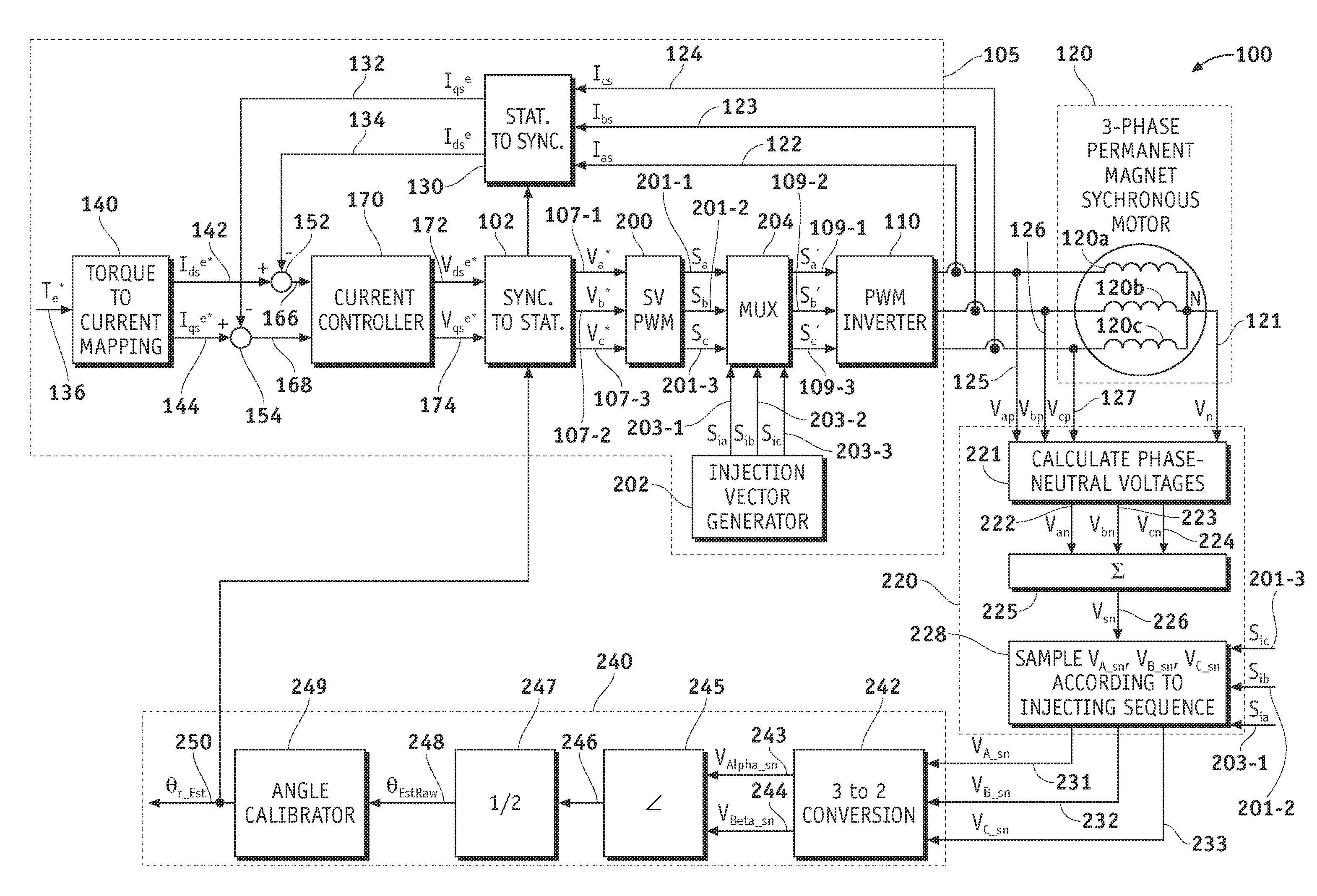
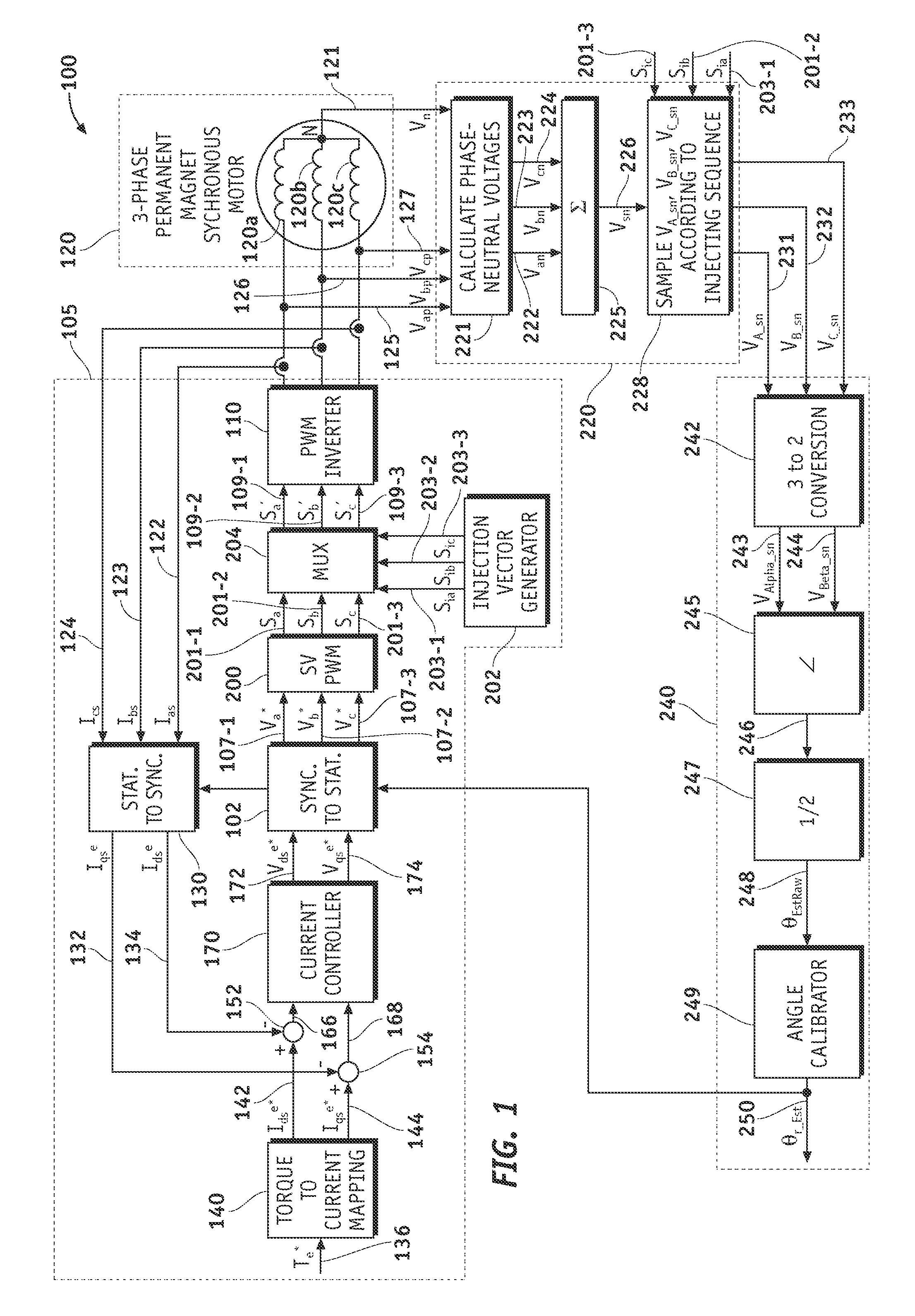
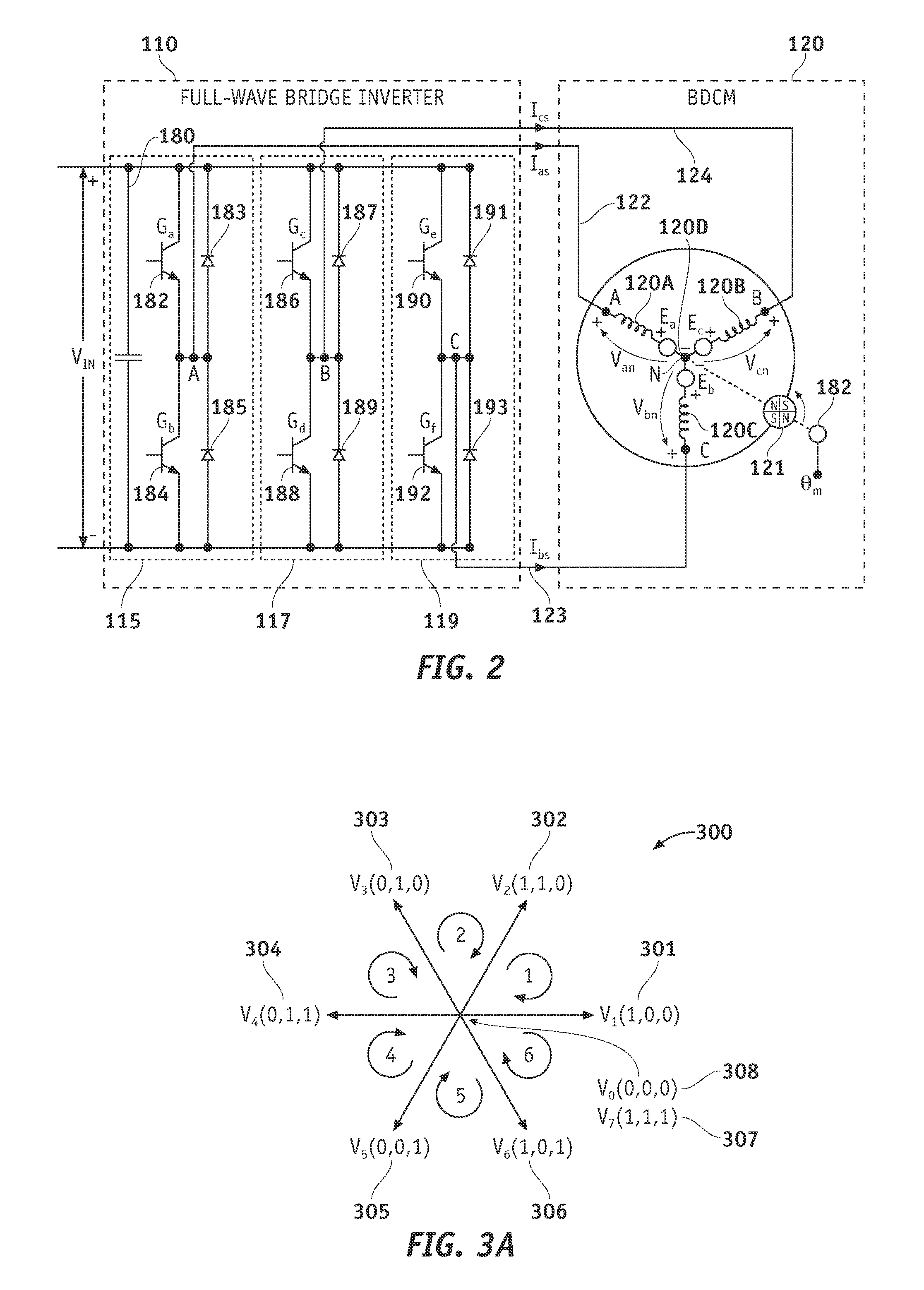
[0014]According to one embodiment a vector controlled motor drive system is provided that enables sensorless estimation of a rotor's angular position with reduced switching losses. The system includes an AC machine, an inverter module coupled to the AC machine, a test vector and duty cycle generator module coupled to the inverter module, a zero-sequence voltage generator module coupled to the AC machine and the inverter module, and an output module coupled to the zero-sequence voltage generator module.
[0016]The first, second and third modified switching vector signal are generated by injecting test pulses into PWM waveforms corresponding to conventional switching vector signals. Injecting test pulses into PWM waveforms causes additional transitions in the resulting modified switching vector signal, but as will be explained below, the modified switching vector signals in accordance with the disclosed embodiments exhibit a decreased number of transitions in comparison to switching vector signals that are used in conventional systems. For example, the first, second and third modified switching vector signal each have an amplitude value that changes between a high value and a low value during each PWM cycle, and over three consecutive PWM cycles, the number of transitions by the first modified switching vector signal between the low value and the high value (and vice-versa) is greater than six and less than twelve. Because the number of transitions is reduced, the number of times the switches in the inverter module switch during each PWM cycle are correspondingly reduced. As such, the disclosed embodiments can significantly reduce the switching losses incurred by the introduction or insertion of the test vectors into each PWM cycle, while maintaining full functionality in comparison to conventional sensorless rotor angular position estimation techniques.

Problems solved by technology

A high performance drive system requires a speed or position sensor which is an expensive component.
Moreover, the circuitry required to process its signals can also be expensive.
The presence of the speed / position sensor in the system adds cost, size, and weight, and reduces reliability as well.
However, Surface Mount Permanent Magnet (SMPM) machines have no intentionally designed saliency and therefore require a very high magnitude injection signal in order to retrieve the position information.
Thus, due to additional losses and noise generated by such a high magnitude injection signal, this method is not suitable for SMPM type application.
However, a traction machine has low inductance and not controlling current during test period may result in an uncontrolled condition.
While the conventional sensorless rotor angular position estimation techniques described above can provide a high fidelity estimate of the rotor position, there are some drawbacks.
One such drawback relates to the increase in switching losses incurred in the semiconductor devices due to the introduction of test vectors injected within each PWM cycle or period.

Method used


Image

  • Methods, systems and apparatus for sensorless rotor angular position estimation implementing reduced switching loss pulse width modulated (PWM) waveforms
  • Methods, systems and apparatus for sensorless rotor angular position estimation implementing reduced switching loss pulse width modulated (PWM) waveforms
  • Methods, systems and apparatus for sensorless rotor angular position estimation implementing reduced switching loss pulse width modulated (PWM) waveforms

Examples


first embodiment

ive Vectors and Trailing Edge Test Vectors

[0128]FIG. 7A is a graph showing PWM waveforms (Dia, Dib and Dic) that include complementary test vectors used in accordance with a first embodiment of the present invention. The test pulses in FIG. 7A define a pair of complementary test vectors (V4 / V1; V6 / V3; V2 / V5) in each PWM cycle / period. FIG. 7B is a graph showing synthesized PWM waveforms of the modified switching vector signals (Da*, Db* and Dc*) 209-1 . . . 209-3 in a sensorless position estimation technique in accordance with a first embodiment of the present invention. The modified switching vector signals (Da*, Db* and Dc*) 209-1 . . . 209-3 are used as gate commands to drive the gates (Ga . . . Gf) of switches 182, 184, 186, 188, 190, 192 in the three-phase voltage source inverter 110. As in FIG. 4B, the PWM waveforms in FIGS. 7A and 7B are those corresponding to sector one (1) in FIG. 3; however, in contrast to FIG. 4B it is noted that three PWM cycles are illustrated (as oppose...

second embodiment

ive Vectors and Leading Edge Test Vectors

[0137]FIG. 8A is a graph showing PWM waveforms (Dia, Dib and Dic) that include complementary test vectors in accordance with a second embodiment of the present invention. The test pulses in FIG. 8A define a pair of complementary test vectors (V1 / V4; V3 / V6; V5 / V2) in each PWM cycle / period. FIG. 8B is a graph showing synthesized PWM waveforms of the modified switching vector signals (Da*, Db* and Dc*) 209-1 . . . 209-3 in a sensorless position estimation technique in accordance with a second embodiment of the present invention. The modified switching vector signals (Da*, Db* and Dc*) 209-1 . . . 209-3 are used as gate commands to drive the gates (Ga . . . Gf) of switches 182, 184, 186, 188, 190, 192 in the three-phase voltage source inverter 110. As in FIG. 4B, the PWM waveforms in FIGS. 8A and 8B are those corresponding to sector one (1) in FIG. 3; however, in contrast to FIG. 4B it is noted that three PWM cycles are illustrated (as opposed to...

third embodiment

Vector in One of the PWM Cycles as One of the Test Vectors

[0144]FIG. 9A is a graph showing PWM waveforms (Dia, Dib and Dic) that include complementary test vectors used in accordance with a third embodiment of the present invention. The test pulses in FIG. 9A define a pair of complementary test vectors (V1 / V4; V6 / V3; V2 / V5) in each PWM cycle / period. FIG. 9B is a graph showing synthesized PWM waveforms of the modified switching vector signals (Da*, Db* and Dc*) 209-1 . . . 209-3 in a sensorless position estimation technique in accordance with a third embodiment of the present invention. The modified switching vector signals (Da*, Db* and Dc*) 209-1 . . . 209-3 are used as gate commands to drive the gates (Ga . . . Gf) of switches 182, 184, 186, 188, 190, 192 in the three-phase voltage source inverter 110. As in FIG. 4B, the PWM waveforms in FIGS. 9A and 9B are those corresponding to sector one (1) in FIG. 3; however, in contrast to FIG. 4B it is noted that three PWM cycles are illust...


PUM


Abstract

Methods, system and apparatus are provided for low speed sensorless rotor angular position estimation that implements reduced switching loss PWM waveforms.

Description

TECHNICAL FIELD[0001]The present invention generally relates to hybrid and electric vehicle power systems, and more particularly relates to techniques for estimating angular position of a rotor without sensors.BACKGROUND OF THE INVENTION[0002]Hybrid and electric vehicles (HEVs) typically include an electric traction drive system that includes an alternating current (AC) electric motor which is driven by a power converter with a direct current (DC) power source, such as a storage battery. Motor windings of the AC electric motor can be coupled to inverter sub-modules of a power inverter module (PIM). Each inverter sub-module includes a pair of switches that switch in a complementary manner to perform a rapid switching function to convert the DC power to AC power. This AC power drives the AC electric motor, which in turn drives a shaft of HEV's drivetrain. Traditional HEVs implement two three-phase pulse width modulated (PWM) inverter modules and two three-phase AC machines (e.g., AC m...

Claims


Application Information

Patent Timeline
Patent Type & Authority Applications(United States)
IPC IPC(8): H02P21/04H02P6/18
CPCB60L15/025B60L15/08B60L2260/44H02P6/182B60L2200/26H02P21/04H02P21/146H02P27/08Y02T10/643H02P21/0039H02P21/18H02P21/24Y02T10/64
Inventor SCHULZ, STEVEN E.SON, YO CHANPATEL, NITINKUMAR R.
Owner GM GLOBAL TECH OPERATIONS LLC
Learn More