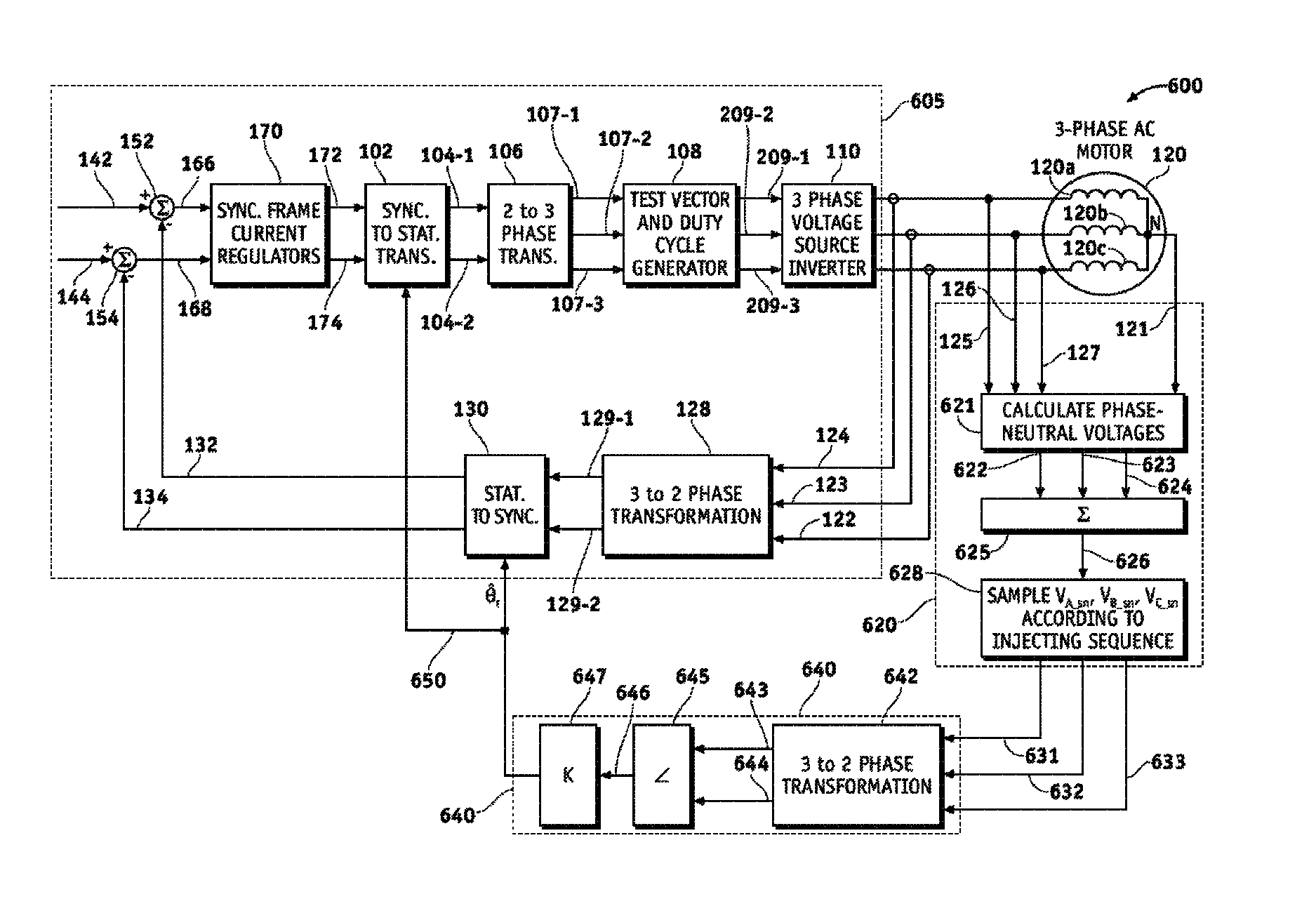
Vector controlled motor drive system implementing pulse width modulated (PWM) waveforms
a technology of pulse width and waveform, which is applied in the direction of electric generator control, dynamo-electric converter control, dynamo-electric gear control, etc., can solve the problems of increasing cost, size, weight, and cost, and the circuitry required to process the signals can also be expensive, so as to reduce the number of transitions and reduce the number of times the switch in the inverter module switches during each pwm cycle , the effect of reducing the number of transition
- Summary
- Abstract
- Description
- Claims
- Application Information
AI Technical Summary
Benefits of technology
Problems solved by technology
Method used
Image
Examples
first embodiment
Leading Edge Active Vectors and Trailing Edge Test Vectors
[0129]FIG. 7A is a graph showing PWM waveforms (Dia, Dib and Dic) that include complementary test vectors used in accordance with a first embodiment of the present invention. The test pulses in FIG. 7A define a pair of complementary test vectors (V4 / V1; V6 / V3; V2 / V5) in each PWM cycle / period. FIG. 7B is a graph showing synthesized PWM waveforms of the modified switching vector signals (Da*, Db* and Dc*) 209-1 . . . 209-3 in a sensorless position estimation technique in accordance with a first embodiment of the present invention. The modified switching vector signals (Da*, Db* and Dc*) 209-1 . . . 209-3 are used as gate commands to drive the gates (Ga . . . Gf) of switches 182, 184, 186, 188, 190, 192 in the three-phase voltage source inverter 110. As in FIG. 4B, the PWM waveforms in FIGS. 7A and 7B are those corresponding to sector one (1) in FIG. 3; however, in contrast to FIG. 4B it is noted that three PWM cycles are illust...
second embodiment
Trailing Edge Active Vectors and Leading Edge Test Vectors
[0138]FIG. 8A is a graph showing PWM waveforms (Dia, Dib and Dic) that include complementary test vectors in accordance with a second embodiment of the present invention. The test pulses in FIG. 8A define a pair of complementary test vectors (V1 / V4; V3 / V6; V5 / V2) in each PWM cycle / period. FIG. 8B is a graph showing synthesized PWM waveforms of the modified switching vector signals (Da*, Db* and Dc*) 209-1 . . . 209-3 in a sensorless position estimation technique in accordance with a second embodiment of the present invention. The modified switching vector signals (Da*, Db* and Dc*) 209-1 . . . 209-3 are used as gate commands to drive the gates (Ga . . . Gf) of switches 182, 184, 186, 188, 190, 192 in the three-phase voltage source inverter 110. As in FIG. 4B, the PWM waveforms in FIGS. 8A and 8B are those corresponding to sector one (1) in FIG. 3; however, in contrast to FIG. 4B it is noted that three PWM cycles are illustrat...
third embodiment
Using an Active Vector in One of the PWM Cycles as One of the Test Vectors
[0145]FIG. 9A is a graph showing PWM waveforms (Dia, Dib and Dic) that include complementary test vectors used in accordance with a third embodiment of the present invention. The test pulses in FIG. 9A define a pair of complementary test vectors (V1 / V4; V6 / V3; V2 / V5) in each PWM cycle / period. FIG. 9B is a graph showing synthesized PWM waveforms of the modified switching vector signals (Da*, Db* and Dc*) 209-1 . . . 209-3 in a sensorless position estimation technique in accordance with a third embodiment of the present invention. The modified switching vector signals (Da*, Db* and Dc*) 209-1 . . . 209-3 are used as gate commands to drive the gates (Ga . . . Gf) of switches 182, 184, 186, 188, 190, 192 in the three-phase voltage source inverter 110. As in FIG. 4B, the PWM waveforms in FIGS. 9A and 9B are those corresponding to sector one (1) in FIG. 3; however, in contrast to FIG. 4B it is noted that three PWM c...
PUM
 Abstract
Description
Claims
Application Information
 - R&D
- Intellectual Property
- Life Sciences
- Materials
- Tech Scout
- Unparalleled Data Quality
- Higher Quality Content
- 60% Fewer Hallucinations
Browse by: Latest US Patents, China's latest patents, Technical Efficacy Thesaurus, Application Domain, Technology Topic, Popular Technical Reports.
© 2025 PatSnap. All rights reserved.Legal|Privacy policy|Modern Slavery Act Transparency Statement|Sitemap|About US| Contact US: help@patsnap.com


