Eureka AIR delivers breakthrough ideas for toughest innovation challenges, trusted by R&D personnel around the world.

Synchronous circuit for use in optical homodyne receiver for generating local oscillation light with accurate demodulation

a technology of synchronous circuit and local oscillation light, which is applied in the direction of light demodulation, transmission monitoring/testing/fault measurement system, instruments, etc., can solve the problems of many research problems that remain unsolved, the multiplication is difficult to implement through current electronic devices, and the generation of harmonics involves many research problems. , to achieve the effect of improving demodulation accuracy and high accuracy

Inactive Publication Date: 2011-01-13
OKI ELECTRIC IND CO LTD
View PDF3 Cites 14 Cited by
  • Summary
  • Abstract
  • Description
  • Claims
  • Application Information

AI Technical Summary

Benefits of technology

[0020]It is therefore an object of the present invention to provide a synchronous circuit for use in an optical homodyne receiver for generating a local oscillation light phase-locked in higher accuracy to render demodulation accuracy improved even in the case of very high carrier frequency such as several hundred THz.
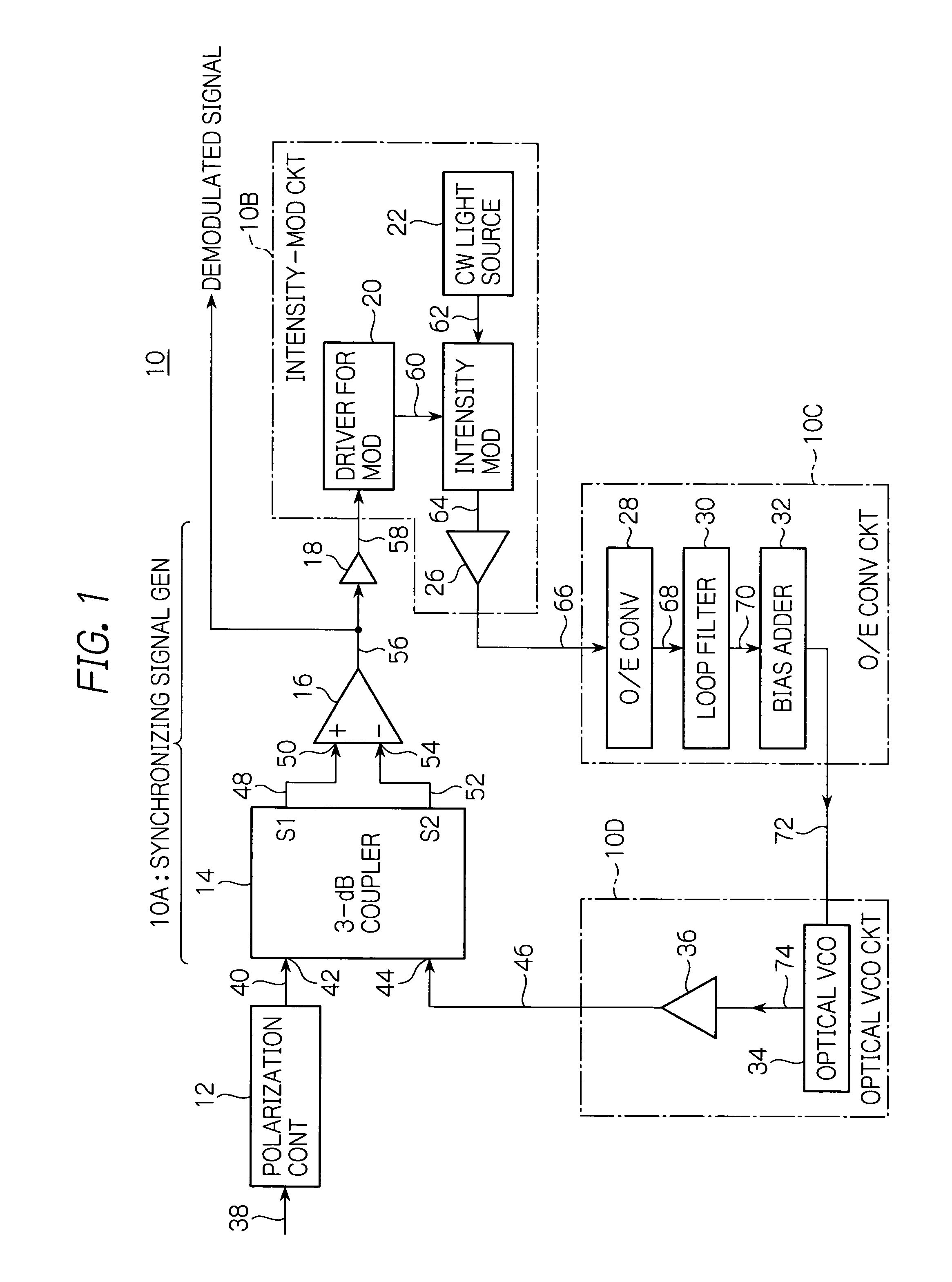
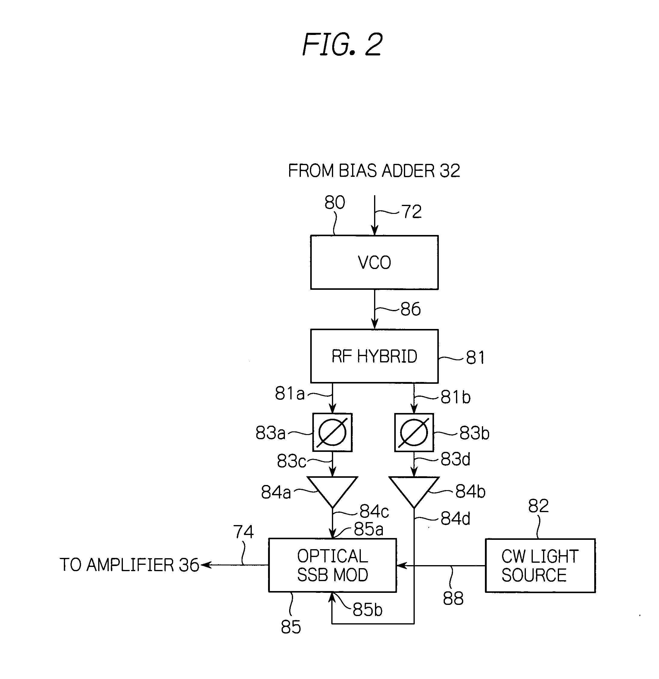
[0022]In accordance with the present invention, a synchronizing signal generator combines either of a received optical BPSK signal and a received local oscillation light with a phase-shifted signal to generate a plurality of different optical signals, at least one of which for use in generating a signal demodulated from the optical BPSK signal is square-law detected, calculates the square-law detected optical signals to convert the obtained optical signal into an electric signal, and produces an electric phase-locking signal which will be a demodulated signal from the optical BPSK signal on the basis of the converted electric signal. The phase-locking signal is used as a modulating signal by an intensity-modulating circuit to modulate an incident continuous light into an optical intensity-modulated signal, which is optoelectrically converted and square-law detected by an optoelectric converting circuit. The square-law detected signal is used by an optical VCO circuit as a phase error signal to adjust a phase or frequency of the local oscillation light to be generated. The local oscillation light with its phase or frequency thus adjusted is supplied to the synchronizing signal generator. The phase error signal can thus be obtained without using an electric multiplier. As a result, even for a signal modulated with an enormously high carrier frequency to which an electric multiplier cannot be applied, the local oscillation light in accurate synchronization can be generated with the accuracy of demodulation improved. In the case of Costas loop, in order to multiply outputs from accurately symmetrical circuits, the skew of an I-axis and a Q-axis of the circuitry is required to be adjusted. However, the present invention does not require, or at least can minimize, elements or portions which need accurate adjustment.

Problems solved by technology

However, in the optical communications using a carrier frequency of several hundred THz, it is difficult to use these solutions without modification.
However, such multiplication is difficult to implement by means of currently existing electronic devices due to physical characteristic requirements of circuit components involved in the configuration.
However, the generation of harmonics involves many research issues remain unsolved such as difficulties about a wavelength region and conversion efficiency.
Therefore, this solution is difficult to reduce to practice.
That results in a fluctuation in phase difference, deteriorating the stability of phase locking.
Such an increase in bit rate reveals waveform distortion and S / N (signal-to-noise) deterioration per length of transmission.
In order to apply the Costas loop stated above to such optical transmission systems, it would be difficult to implement phase locking unless the multiplier has its operable frequency band entirely falling within the baseband of a signal to be demodulated.
As a result, the multiplier develops on its output a result from multiplying these smoothed signals with each other, which does not accurately reflect the phase error.
Therefore, with the optical communications, it is difficult to maintain a stable operation.
However, currently available electronic device technology fails to easily configure such a multiplier.
However, seldom reports are found on an optical PLL (Phase-Locked Loop) which stably operates on a BPSK signal having a high bit rate over several ten bps.
Furthermore, in a Costas loop, when the I-axis and Q-axis components of a signal are not accurately in phase with each other, a result from the multiplying does not reflect the phase error.
In addition to this, the group delay characteristic of an amplifier or the like included in these sections also raises harmful effects.
Thus, such a solution of multiplying the outputs from the circuits symmetrically structured makes the circuit designing more difficult in practice, and has prevented dissemination of a homodyne system having the highest performance in optical coherent communication.

Method used


Image

  • Synchronous circuit for use in optical homodyne receiver for generating local oscillation light with accurate demodulation
  • Synchronous circuit for use in optical homodyne receiver for generating local oscillation light with accurate demodulation
  • Synchronous circuit for use in optical homodyne receiver for generating local oscillation light with accurate demodulation

Examples


Embodiment Construction

[0030]Well, reference will be made to accompanying drawings to describe in detail a synchronous circuit of an optical homodyne receiver in accordance with preferred embodiments of the present invention. With reference first to FIG. 1, a synchronous circuit 10 for use in an optical homodyne receiver in accordance with a preferred embodiment generally includes: a synchronizing signal generator 10A adapted to combine a received optical BPSK signal 40 with a received local oscillation light 44, either of which the generator 10A may shift in phase, to thereby produce a plurality of different optical signals, among which optical signals 48 and 52 for use in producing a signal demodulated from the optical BPSK signal are square-law detected, optical signals resultant from the square-law detection being operated and converted to an electric signal 56, from which a phase-locking electric signal 58 is produced which may be used as a signal demodulated from the optical BPSK signal; an intensit...


PUM


Abstract

In a synchronous circuit, a synchronizing signal generator combines either an optical BPSK signal or local oscillation light with a phase-shifted signal to produce different optical signals, one of which for use in producing a signal demodulated from the BPSK signal is square-law detected, and calculates the optical signal detected to convert the signal into an electric signal. The generator produces an electric phase-locking signal which will be a demodulated signal from the BPSK signal on the basis of the electric signal. The phase-locking signal is used as a modulating signal by an intensity-modulating circuit to modulate an incident continuous light into an optical intensity-modulated signal, which is optoelectrically converted and square-law detected by an optoelectric converter. The converted signal is used by an optical VCO circuit as a phase error signal to adjust the phase or frequency of the local oscillation light, which is supplied to the signal generator.

Description

BACKGROUND OF THE INVENTION[0001]1. Field of the Invention[0002]The present invention relates to an optical homodyne receiver, and more particularly a synchronous circuit for use in an optical homodyne receiver adapted to receive an optical signal modulated, for example, by BPSK (Binary Phase-Shift Keying).[0003]2. Description of the Background Art[0004]With a recent increase in optical communications capacity, active research has been concentrated on the phase modulation such as NRZ (Non-Return-to-Zero)-BPSK, which is more advantageous in signal-to-noise ratio than the conventional intensity modulation. Different from the conventional intensity modulation of directly modulating the intensity of a light, the phase modulation utilizes the coherence of light so as to render its phase convey information to be transmitted to thereby forward the information.[0005]In coherent communication systems, receiver schemes such as heterodyne and homodyne detections have predominantly been propose...

Claims


Application Information

Patent Timeline
IPC IPC(8): H04B10/06H04B10/516G02F2/00H04B10/07H04B10/54H04B10/556H04B10/588H04B10/61
CPCH04B10/63H04B10/61
Inventor FUJII, AKIHIRO
Owner OKI ELECTRIC IND CO LTD
Why Eureka
Eureka Blog
Learn More