
Methods for performing biometric recognition of a human eye and corroboration of same

a biometric recognition and human eye technology, applied in the field of biometric recognition of human eye and corroboration of same, can solve the problems of time required to obtain and process data, the possibility of spoofing, and the irritation a person may feel, and achieve the effect of simple approach and placement of leds

Active Publication Date: 2011-01-13
EYELOCK
View PDF31 Cites 108 Cited by
  • Summary
  • Abstract
  • Description
  • Claims
  • Application Information

AI Technical Summary

Benefits of technology

"The invention is about a system for detecting a human eye using a computer screen and a camera. The system analyzes the image of the eye and compares it to a reference image to determine if there is a reflection that matches the eye. The system can detect the eye based on the size and shape of the reflected image. The technical effect of the invention is to provide a reliable and accurate method for detecting the human eye for various applications such as security systems or access control."

Problems solved by technology

One problem faced by iris recognition systems involves the possibility of spoofing.
One disadvantage of this type of system involves the time required to obtain and process data as well as the irritation a person may feel in response to having a light of varying intensity shone into their eye.
One disadvantage of this system, involves the simplicity of the approach and the placement of the LED's.
Also, while this system may operate more quickly than systems that dilate a pupil, it still requires time to capture at least two separate images: one when each of the two LED's are individually lit.
However since the iris patterns are not easily recognizable to a human, it is impossible to demonstrate to a user who has been rejected from any iris recognition system the reason for the rejection.

Method used


Image

  • Methods for performing biometric recognition of a human eye and corroboration of same
  • Methods for performing biometric recognition of a human eye and corroboration of same
  • Methods for performing biometric recognition of a human eye and corroboration of same

Examples


example implementation

[0082 Methods

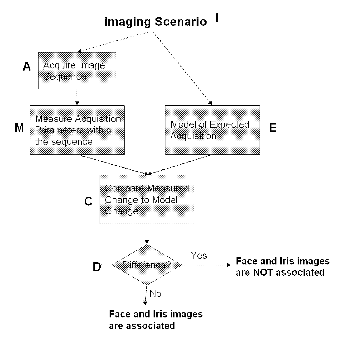
[0083]There are many methods for performing steps M,E,C,D in FIG. 5. We present a preferred set of methods as an example. First, if the images acquired in step A are labeled I1,I2,I3,I4 etc., then a difference image sequence D1,D2,D3,D4 is computed by subtracting adjacent frames. For example, D1=I2−I1, and D2=I3−I2 etc. If the camera sensor is stationary, then this differencing removes the background from processing meaning that all resultant intensities in the sequence are due to the moving person. Note that this approach is only used if only the user is moving. In cases of a lens that zooms, this step would not be performed since the background also moves. Second, flow analysis is performed between successive image pairs. There are many methods known in the art for performing flow analysis. An example is Bergen et. al, “Hierarchical Motion Analysis”, European Conference on Computer Vision, 1992. We compute both flow values and also confidence measures in the flow at e...


PUM


Abstract

A method of biometric recognition is provided. Multiple images of the face or other non-iris image and iris of an individual are acquired. If the multiple images are determined to form an expected sequence of images, the face and iris images are associated together. A single camera preferably acquires both the iris and face images by changing at least one of the zoom, position, or dynamic range of the camera. The dynamic range can be adjusted by at least one of adjusting the gain settings of the camera, adjusting the exposure time, and / or adjusting the illuminator brightness. The expected sequence determination can be made by determining if the accumulated motion vectors of the multiple images is consistent with an expected set of motion vectors and / or ensuring that the iris remains in the field of view of all of the multiple images.

Description

RELATED APPLICATIONS[0001]This is a continuation-in-part of U.S. patent Ser. No. 11 / 559,381 filed Nov. 13, 2006, and entitled “Apparatus and Methods for Detecting The Presence of a Human Eye”, issuing as U.S. Pat. No. 7,801,335 on Sep. 21, 2010, the entirety of which is incorporated by reference herein, which in turn claims the benefits of priority to U.S. provisional patent application No. 60 / 597,130 filed on Nov. 11, 2005, and U.S. provisional patent No. 60 / 597,152 filed on Nov. 14, 2005, and U.S. provisional patent No. 60 / 597,231, filed on Nov. 17, 2005, and U.S. provisional patent No. 60 / 597,289, filed on Nov. 21, 2005 and U.S. provisional patent No. 60 / 597,336 filed on Nov. 25, 2005. Each of these is incorporated herein by reference in their entirety.BACKGROUND OF THE INVENTION[0002]1. Field of the Invention[0003]The invention relates generally to systems in which imagery is acquired primarily to determine or verify the identity of a person using a biometric recognition system,...

Claims


Application Information

Patent Timeline
Patent Type & Authority Applications(United States)
IPC IPC(8): G06T7/20G06T7/00G06V10/141H04N7/18
CPCG06K9/00604H04N5/23219G06K9/00906G06K9/00899G06V40/165G06V40/19G06V40/40G06V40/70G06V40/45G06V10/141H04N23/611G06V40/197G06V40/161G06F18/22G06T7/20
Inventor HANNA, KEITH J.HOYOS, HECTOR T.
Owner EYELOCK
Learn More