
Enhancement of thermal interface conductivities with carbon nanotube arrays

a technology of carbon nanotubes and thermal interfaces, applied in the field of thermal interfaces, can solve problems such as the reduction of interfacial thermal resistance, and achieve the effects of improving interface performance and life, increasing the effective thermal contact conductance of the thermal interface, and high thermal contact conductan

Active Publication Date: 2011-01-13
PURDUE RES FOUND INC
View PDF12 Cites 36 Cited by
  • Summary
  • Abstract
  • Description
  • Claims
  • Application Information

AI Technical Summary

Benefits of technology

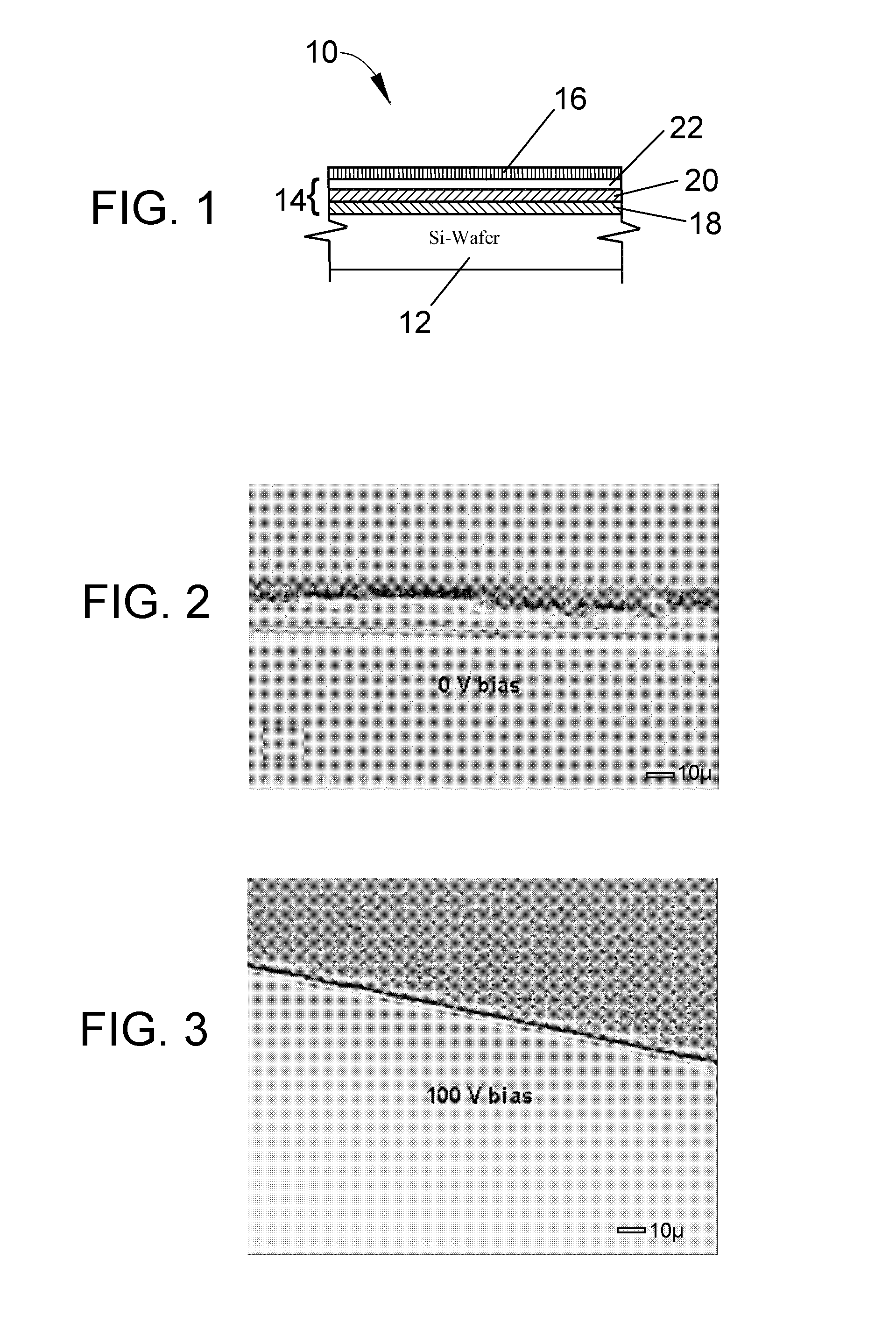
[0010]The above aspects of the invention are believed to provide a number of advantages, depending on the characteristics of the thermal interfaces in which they are used. For example, the continuous array of carbon nanotubes can be used as the sole thermal interface material within a thermal interface, providing a dry contact between contact surfaces with very high thermal contact conductance. Alternatively, the continuous array of carbon nanotubes can be used in combination with a solid or flowable thermal interface material (TIM). If used with a flowable TIM, the well-anchored CNT array has been unexpectedly found to inhibit the pumping out effect to which the flowable TIM is subject to improve the interface performance and life by maintaining a continuous layer of the flowable TIM of desirable thickness, even under high pressure, high temperature, and load cycling. The inclusion of a well-anchored CNT array is also believed to increase the effective thermal contact conductance of the thermal interface. Finally, a dramatic improvement in the performance of carbon nanotube arrays as a TIM is believed to be attributable to the multilayer anchoring structure, and particularly the innermost titanium layer that is believed to provide a stronger bond that promotes a more efficient heat-flow path at the interfaces between the substrate and individual CNT's.

Problems solved by technology

Reduction of interfacial thermal resistance remains a major challenge in the thermal management of many heat-generating engineered components and systems, including the chip-package interface of semiconductor devices, for example, a power integrated circuit (IC) and a heat sink or substrate.

Method used


Image

  • Enhancement of thermal interface conductivities with carbon nanotube arrays
  • Enhancement of thermal interface conductivities with carbon nanotube arrays
  • Enhancement of thermal interface conductivities with carbon nanotube arrays

Examples


Embodiment Construction

[0023]The present invention provides the capability for thermal interface materials (TIM's) with significantly improved performance, and particularly the performance of carbon nanotubes (CNT's) as a TIM. According to one preferred aspect of the invention, performance enhancement is achieved in part with the use of multiple metal layers that, in addition to providing the required surface catalysis for the nanotube growth process, form an anchoring structure that improves the bond with the CNT's manifested by a more efficient heat-flow path at the CNT-substrate interface. According to another preferred aspect of the invention, performance enhancement is achieved by synthesizing the CNT's to ensure that a dense, vertically-oriented array forms, as opposed to randomly oriented CNT's or isolated bundles of CNT's. Such a CNT array can be combined with a solid or flowable TIM, which in the latter case the CNT array reduces the tendency for the flowable TIM to be pumped out from between a p...


PUM

PropertyMeasurementUnit
Fractionaaaaaaaaaa
Fractionaaaaaaaaaa
Electric potential / voltageaaaaaaaaaa

Abstract

A method of forming a well-anchored carbon nanotube (CNT) array, as well as thermal interfaces that make use of CNT arrays to provide very high thermal contact conductance. A thermal interface is formed between two bodies by depositing a continuous array of carbon nanotubes on a first of the bodies so that, on mating the bodies, the continuous array is between surface portions of the first and second bodies. The thermal interface preferably includes a multilayer anchoring structure that promotes anchoring of the continuous array of carbon nanotubes to the first body. The anchoring structure includes a titanium bond layer contacting the surface portion of the first body, and an outermost layer with nickel or iron catalytic particles from which the continuous array of carbon nanotubes are nucleated and grown. Additional thermal interface materials (TIM's) can be used in combination with the continuous array of carbon nanotubes.

Description

CROSS REFERENCE TO RELATED APPLICATIONS[0001]This application claims the benefit of U.S. Provisional Application No. 60 / 706,203, filed Aug. 5, 2005, the contents of which are incorporated herein by reference.BACKGROUND OF THE INVENTION[0002]The present invention generally relates to thermal interfaces across which heat is transferred. More particularly, this invention relates to the enhancement of heat transfer across a thermal interface through the inclusion of carbon nanotubes.[0003]Reduction of interfacial thermal resistance remains a major challenge in the thermal management of many heat-generating engineered components and systems, including the chip-package interface of semiconductor devices, for example, a power integrated circuit (IC) and a heat sink or substrate. Thermal contact resistance exists at interfaces because of imperfections caused by microscopic asperities between contacting surfaces. Thermal interface materials (TIM's), such as solders, thermal greases, oils, ge...

Claims


Application Information

Patent Timeline
IPC IPC(8): H05K7/20B32B5/02B32B9/00B32B37/02
CPCH01L23/373H01L2924/10253H01L2924/0002Y10S977/742Y10T428/12625Y10T428/24174Y10T156/10Y10T428/30Y10T428/24851Y10S977/762H01L2924/00
Inventor XU, JUNFISHER, TIMOTHY S.
Owner PURDUE RES FOUND INC
Learn More