
Depolarizing film, process for producing the same, and liquid-crystal display

a technology of liquid crystal display and depolarizing film, which is applied in the direction of polarising elements, instruments, optical elements, etc., can solve the problems of poor productivity, difficult mass production of calcite, etc., and achieve excellent productivity, large area, and excellent product quality.

Inactive Publication Date: 2011-01-13
NITTO DENKO CORP
View PDF3 Cites 5 Cited by
  • Summary
  • Abstract
  • Description
  • Claims
  • Application Information

AI Technical Summary

Benefits of technology

[0015]According to the present invention, it is possible to provide a depolarizing film which is excellent in productivity and can have a large area, a process for producing the same, and a liquid-crystal display using such a depolarizing film.
[0016]The present inventors have extensively studied in order to achieve the above object, and as a result have found that the use of birefringent very short fibers instead of inorganic birefringent crystals, such as calcite, for use in conventional depolarizing elements makes it possible to obtain a depolarizing film which is excellent in productivity and can have a large area.
[0017]The birefringent very short fibers to be used in the present invention are obtained by, for example, cutting stretched fibers, and therefore can be cheaply mass-produced. Further, by appropriately adjusting the stretching ratio of fibers, it is also possible to adjust the birefringence of resultant very short fibers. This makes it possible to obtain a depolarizing film having excellent properties.
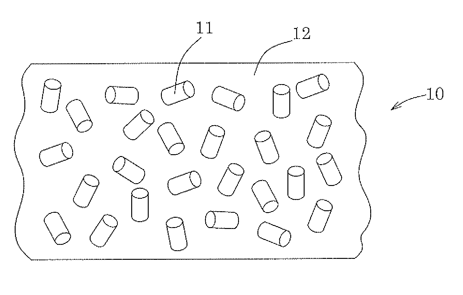
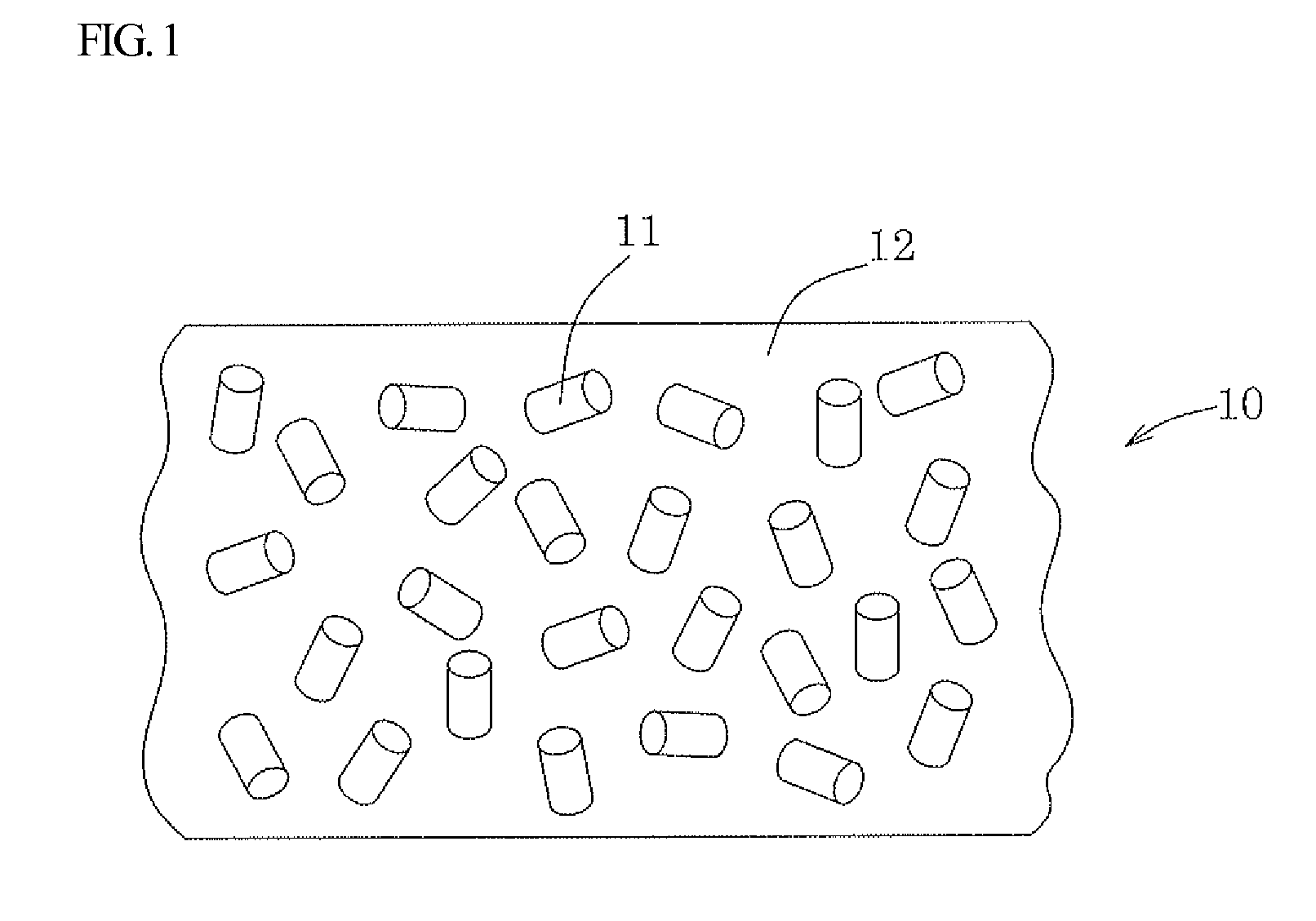
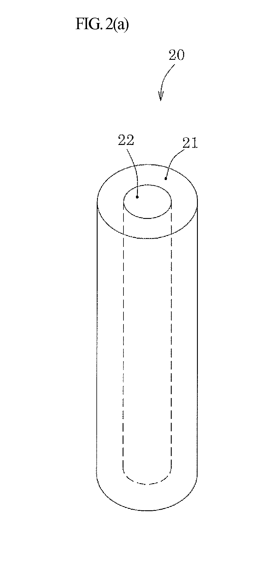
[0018]As shown in FIG. 1, a depolarizing film 10 according to the present invention comprises: a translucent resin film 12; and a plurality of very short fibers 11 dispersed in the translucent resin film 12. By using the very short fibers 11, a three-dimensional random distribution of fiber orientation in the thin depolarizing film 10 can be easily achieved. The very short fibers are birefringent, because the refractive index nA of the very short fibers in the direction of a fiber axis (also referred to as a “major axis direction”) is different from the refractive index nB of the very short fibers in a direction orthogonal to the fiber axis (also referred to as a “minor axis direction”). Such a depolarizing film obtained by dispersing birefringent very short fibers in a translucent resin film can convert incident polarized light into unpolarized light to emit the unpolarized light.
[0019]The very short fibers are preferably dispersed in such a state that the distribution of orientation of the very short fibers (the distribution of orientation of fiber axis (i.e., major axis) of the very short fibers) is random in three dimensions. When the distribution of orientation of the very short fibers is closer to random in three dimensions, depolarization is more completely achieved. The number of the very short fibers oriented in a direction perpendicular to the plane of the film may be relatively small as long as the orientation of the very short fibers is random in the plane of the film.
[0020]The very short fibers to be used in the depolarizing film according to the present invention are usually birefringent, and therefore at least one of the refractive index nA of the very short fibers in the direction of a fiber axis and the refractive index nB of the very short fibers in a direction orthogonal to the fiber axis is different from the average refractive index n0 of the translucent resin. Here, the average refractive index n0of the translucent resin is represented by the formula: (extraordinary refractive index+ordinary refractive index×2) / 3. Therefore, the depolarizing film emits diffusion light, and therefore usually appears cloudy. The depolarizing film has a haze of, for example, 10% to 90%.

Problems solved by technology

As such a birefringent material, calcite has been long known but is difficult to mass-produce.
Therefore, such a conventional depolarizing element has a problem in that it is poor in productivity.

Method used


Image

  • Depolarizing film, process for producing the same, and liquid-crystal display
  • Depolarizing film, process for producing the same, and liquid-crystal display
  • Depolarizing film, process for producing the same, and liquid-crystal display

Examples


example 1

[0061]An ethylene / vinyl alcohol copolymer (manufactured by Nippon Synthetic Chemical Industry Co., Ltd. under the trade name of “SoarnoL DC321B”, melting point: 181° C.) was melted at 270° C., and was then charged into a nozzle for single-structure fiber spinning and spun at a spinning rate of 600 m / min to obtain a spinning filament having a diameter of 30 μm. The spinning filament was stretched 4 times its initial length in warm water at 60° C. to obtain a continuous fiber having a diameter of 15 μm.

[0062]The continuous fibers were arranged in parallel with each other to prepare a fiber bundle. The fiber bundle was embedded and fixed in a polyvinyl alcohol resin and cut by a cutting blade, and then the polyvinyl alcohol resin was melted by warm water and removed to obtain very short fibers having a fiber length of 30 μm.

[0063]A number of the aforementioned very short fibers were prepared, and were then dispersed in a polyester acrylate-based UV-curable resin liquid (manufactured by...

example 2

[0064]An ethylene / vinyl alcohol copolymer (manufactured by Nippon Synthetic Chemical Industry Co., Ltd. under the trade name of “Soarnol DC321B”, melting point: 181° C.) and a propylene-excessive ethylene / propylene copolymer (manufactured by Japan Polypropylene Corporation under the trade name of “OX1066A”, melting point: 138° C.) were melted at 270° C. and 230° C., respectively, and were then charged into a nozzle for sea-island composite fiber spinning (number of islands per fiber cross section: 37) and spun at a spinning rate of 600 m / min to obtain a spinning filament having a diameter of 30 μm.

[0065]The spinning filament was stretched 4 times its initial length in warm water at 60° C. to obtain a continuous fiber having a diameter of 15 μm. The cross section of the continuous fiber was observed with an electron microscope, and as a result it was confirmed that the continuous fiber had a sea-island structure in which cylindrical second birefringent regions (islands, diameter of c...

example 3

[0067]The depolarizing film prepared in Example 2 was attached to the viewer-side surface of a liquid-crystal panel of a commercially-available mobile phone (manufactured by NTT DOCOMO Inc. under the trade name of “FOMA P905i”) to produce a liquid-crystal display. The display characteristics of the liquid-crystal display are shown in Table 3.


PUM

PropertyMeasurementUnit
refractive index nB2aaaaaaaaaa
refractive index n0aaaaaaaaaa
hazeaaaaaaaaaa

Abstract

Disclosed herein is a depolarizing film which is excellent in productivity and can have a large area. The depolarizing film is obtained by using birefringent very short fibers instead of inorganic birefringent crystals, such as calcite, for use in conventional depolarizing elements.

Description

FIELD OF THE INVENTION[0001]The present invention relates to a depolarizing film, a process for producing the same, and a liquid-crystal display using the depolarizing film.DESCRIPTION OF THE RELATED ART[0002]A depolarizing element has the function of converting incident polarized light into unpolarized light to emit the unpolarized light, and is therefore used in measurement instruments using optical fibers or lasers. As a conventional depolarizing element, one obtained by interposing an adhesive, in which fine particles made of a birefringent material are dispersed, between cover glasses is known (Japanese Patent Application Laid-Open Publication No. JP 2-184804 A). As such a birefringent material, calcite has been long known but is difficult to mass-produce. Therefore, such a conventional depolarizing element has a problem in that it is poor in productivity. Under the circumstances, there has been a demand for a novel depolarizing element capable of solving such a problem.SUMMARY...

Claims


Application Information

Patent Timeline
Patent Type & Authority Applications(United States)
IPC IPC(8): G02F1/13363B29D11/00G02B5/30
CPCG02B5/3058G02F2202/40G02B27/0018G02B5/3083
Inventor YONEZAWA, HIDEYUKIMIYATAKE, MINORUNISHIMURA, AKINORI
Owner NITTO DENKO CORP
Learn More