
Multiresonance helix antenna

a multi-resonance helix and antenna technology, applied in the direction of antenna details, non-resonant long antennas, antennas, etc., can solve the problems of increasing the number of components and production stages, requiring separate feed circuits, and small bandwidth

Inactive Publication Date: 2011-01-06
ELEKTROBIT WIRELESS COMM OY
View PDF9 Cites 8 Cited by
  • Summary
  • Abstract
  • Description
  • Claims
  • Application Information

AI Technical Summary

Benefits of technology

[0012]The invention has the advantage that no separate feed circuit for the phase shifts is required in an antenna with plurality of helix radiators. This is due to the positioning of the radiators, the fine tuning of their length and that they are to be fed from above. Another advantage of the invention is that a multi-resonance structure is obtained without separate additional components. A further advantage of the invention is that the characteristic efficiency and good polarization and radiation pattern of the antenna type in question is obtained at each resonance frequency. The antenna structure is simple, in which case its production costs are relatively low.

Problems solved by technology

This means in the case of the satellite communication demanding antenna design because of the long distance between the connection parties.
A problem in the helix antennas is their small bandwidth especially when the helix is made to be small-sized.
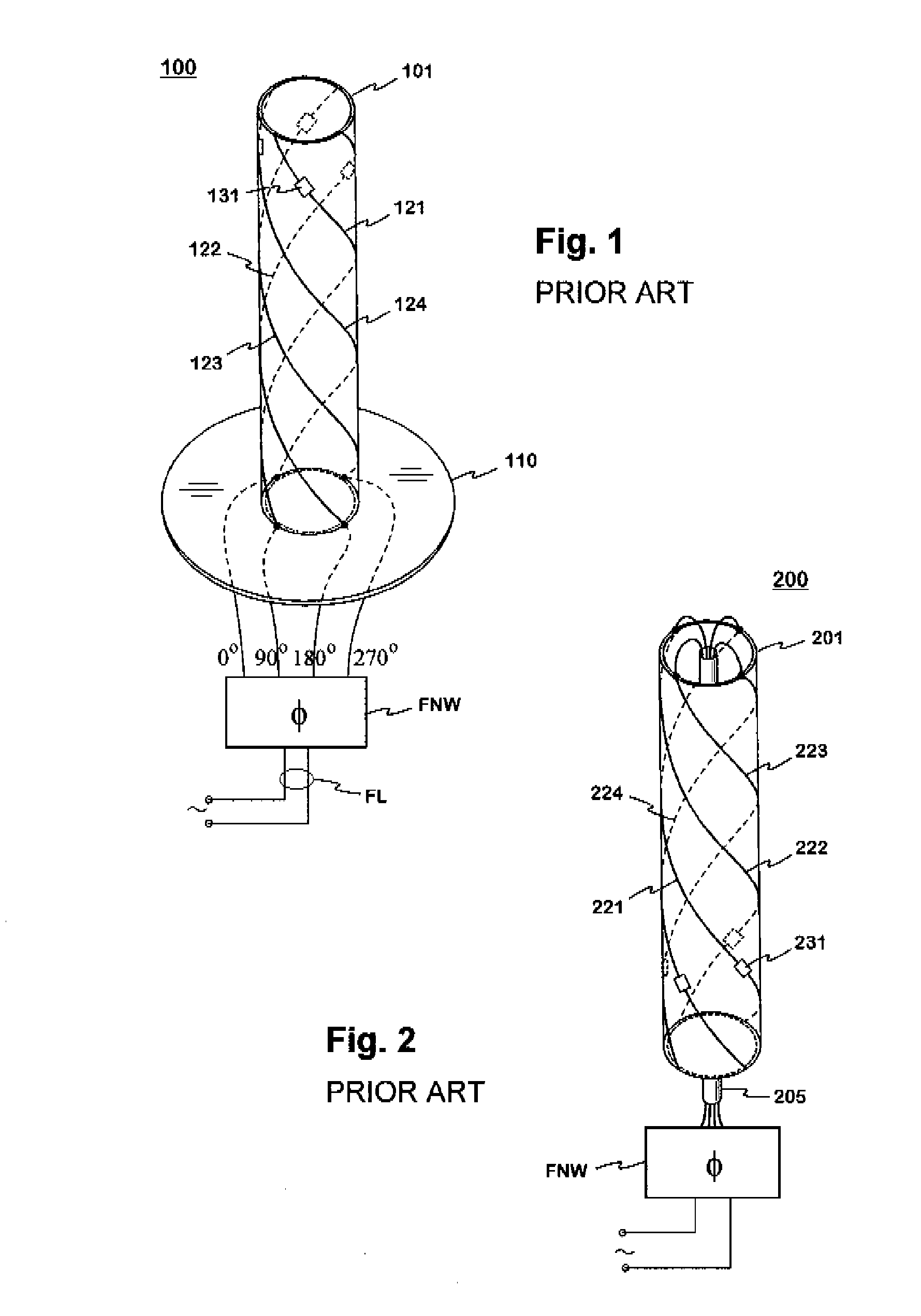
A disadvantage of the structures like in FIGS. 1 and 2 is that a separate feed circuit is required in them for realizing the phase differences.
In addition, the dualband feature requires resonance circuits, which further increases the number of components and production stages.
A disadvantage of the antenna is that its feed requires a phase shift circuit like in the case of FIG. 1.
In addition, the efficiency of the antenna remains relatively low.
A disadvantage of the structures is that it is complicated, which means relatively high production costs.
In addition the quadrafilars degrade the radiation of each other, which lowers the efficiency.

Method used


Image

  • Multiresonance helix antenna
  • Multiresonance helix antenna
  • Multiresonance helix antenna

Examples


Embodiment Construction

[0020]FIGS. 1 and 2 were already described in connection with the description of the prior art.

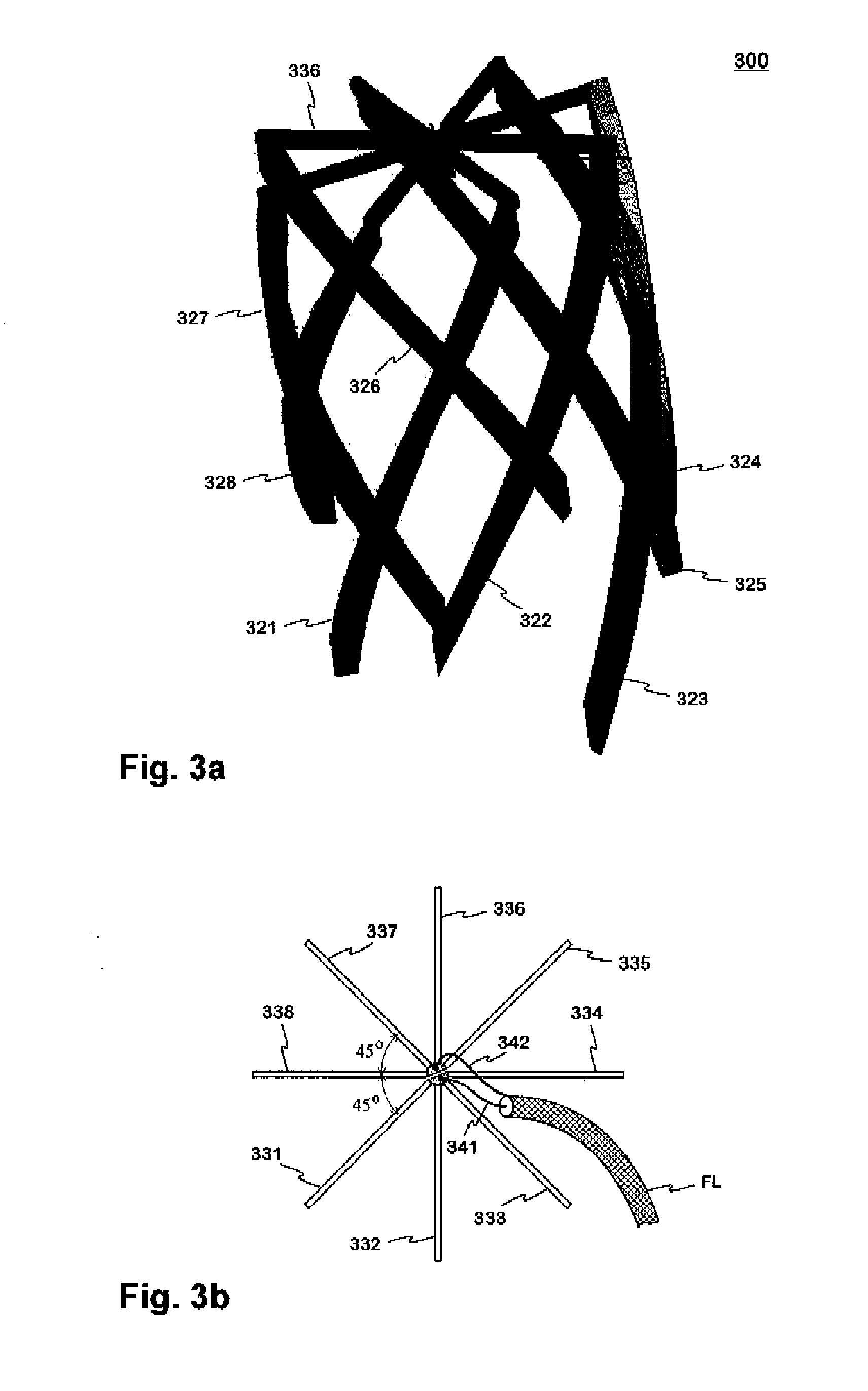
[0021]FIG. 3a shows an example of the helix antenna according to the invention. The antenna 300 comprises eight helical radiators 321-328 side by side on a same geometric cylindrical surface, the antenna then being octafilar by type. ‘Side by side’ means that the radiators start towards the same direction from a substantially same geometric plane perpendicular to the axis of the cylindrical surface, or the antenna axis. Each radiator is supported from its upper end to the antenna hub by a conductive arm, as the arm 336 of the sixth radiator 326. The antenna hub is on the antenna axis at the upper end of the antenna. Each arm functions as the feed conductor of one radiator at the same time, the antenna is then to be fed from above. An arm and a radiator form in this example a rigid object so that the antenna is wholly air-insulated and has no dielectric support parts.

[0022]The radiators are...


PUM


Abstract

A helix antenna for satellite connections of mobile devices is to be fed from above, and all its radiators are side by side on a same geometric cylindrical surface. The antenna has at least two resonances. In the case of two-resonance every second radiator resonates at a lower frequency and the rest of the radiators at another, higher frequency, the frequency difference being based on the difference in the physical length of the radiators. One conductor of the feed line of the antenna is connected directly to one half of the radiators and the other conductor to the other half of the radiators. No separate feed circuit for the phase shifts is required in an antenna with plurality of helix radiators, because the phasing can be implemented by the positioning of the radiators and the fine tuning of their length. The antenna structure is simple, and case its production costs are relatively low.

Description

[0001]The invention relates to a helix antenna, which has at least two usable resonances, the antenna being especially aimed for the satellite connections of mobile devices.BACKGROUND OF THE INVENTION[0002]The antenna of a mobile device has to naturally be relatively small-sized. This means in the case of the satellite communication demanding antenna design because of the long distance between the connection parties. In practice the different helical structures are most common. Beside a reasonable small size, also the circular polarization used generally in the satellite systems and a wide radiation beam are obtained by those structures. A problem in the helix antennas is their small bandwidth especially when the helix is made to be small-sized.[0003]FIGS. 1 and 2 show dualband helix antennas for satellite connections, known from the publication U.S. Pat. No. 6,653,987. The antenna 100 in FIG. 1 comprises four radiating elements, or radiators 121, 122, 123, 124 on the surface of a c...

Claims


Application Information

Patent Timeline
Patent Type & Authority Applications(United States)
IPC IPC(8): H01Q1/36
CPCH01Q1/362H01Q11/08H01Q11/083
Inventor HAARAKANGAS, TUOMO
Owner ELEKTROBIT WIRELESS COMM OY
Learn More