Welding Assembled Structure of Diode in Rectifier for Generator

a technology of diodes and rectifiers, which is applied in the direction of rectification associations, basic electric elements, solid-state devices, etc., can solve the problems of inconvenient assembly, huge labor costs, and inability to meet the requirements of a generator, so as to ensure the performance of the rectifier, reduce labor costs, and reduce labor costs

Inactive Publication Date: 2011-01-06
VICTORY IND CORP
View PDF4 Cites 2 Cited by
  • Summary
  • Abstract
  • Description
  • Claims
  • Application Information

AI Technical Summary

Benefits of technology

[0010]The advantage of the present invention is that the diode is secured in between the solid joint lead and the soldering tag by spot welding from loosening during operation, thereby ensuring the performance of the rectifier. In addition, the narrowed connecting portion of the soldering tag leads to a relatively large resistance thereon when a current flow passes therethrough during spot welding, so as to produce instantaneous high heat that facilitates welding, thereby achieving convenient fabrication. By using spot welding, not only can the process be efficient and fast, but also the manufacture costs can be significantly reduced.
is that the diode is secured in between the solid joint lead and the soldering tag by spot welding from loosening during operation, thereby ensuring the performance of the rectifier. In addition, the narrowed connecting portion of the soldering tag leads to a relatively large resistance thereon when a current flow passes therethrough during spot welding, so as to produce instantaneous high heat that facilitates welding, thereby achieving convenient fabrication. By using spot welding, not only can the process be efficient and fast, but also the manufacture costs can be significantly reduced.

Problems solved by technology

However, the existing rectifiers are designed such that the conjunctive configuration between rectifiers and diode directly affects, among others, the conductivity, stability, and operational performance of the diode.
Given the conventional less-than-perfect corresponding design between a leader frame of a rectifier and pin of a diode, either spot welding or ion welding could only achieve limited effects.
Among known technologies, burning by means of plasma machine to connect diode could achieve good effects; however, both immense costs and labor turn out to be the disadvantages of overall manufacturing costs.

Method used


Image

  • Welding Assembled Structure of Diode in Rectifier for Generator
  • Welding Assembled Structure of Diode in Rectifier for Generator
  • Welding Assembled Structure of Diode in Rectifier for Generator

Examples


Embodiment Construction

[0016]For those skilled in the art to understand the characteristics, contents, advantages, and effects of the present invention, detailed description will be made with reference to drawings appended and through presentation of embodiments. Drawings referred in the present invention are to illustrate and support the application, not necessarily drawn to actual scale or serve as precise arrangement while performing the present invention; thus, it should be appreciated the scale and arrangement of the drawings appended are not to limit the claims when carrying out the present invention.

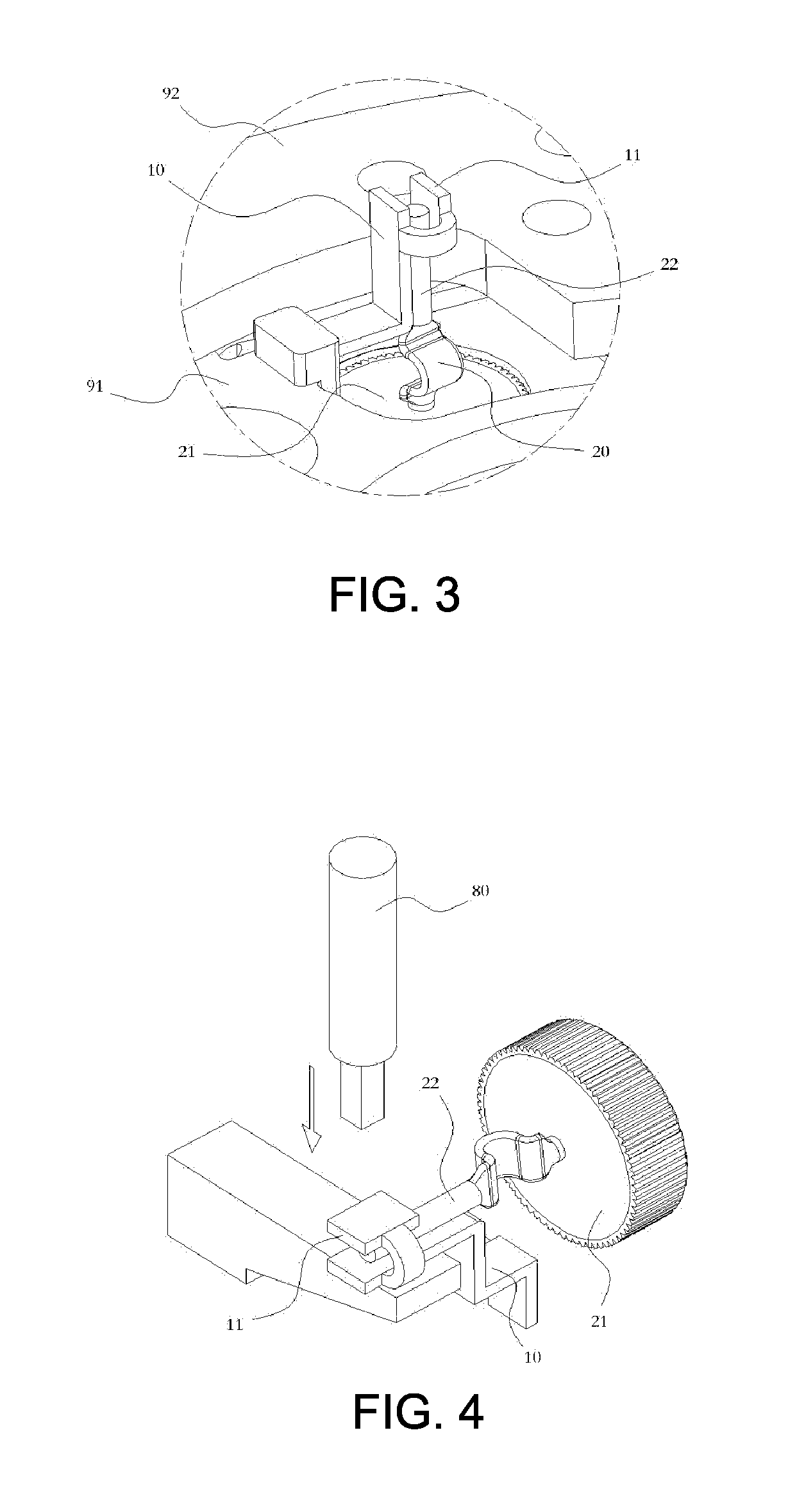
[0017]With reference to FIG. 1 to FIG. 3, a welding assembled structure of a diode in a rectifier for a generator according to one preferred embodiment of the present invention may include a solid joint lead 10 and a diode 20.

[0018]The aforementioned solid joint lead 10 is fixed on a leader frame 91 of the rectifier 90, and is a lengthwise member made of a metal-based conductive material (e.g. copper). ...


PUM


Abstract

A welding assembled structure of a diode in a rectifier is disclosed. Therein, a solid joint lead which is a lengthwise member with one end contacting a leader frame of the rectifier, and an opposite extended end bent and extended outward the leader frame, while having a soldering tag located at one side of the extended end. The diode has a pin with an extended end located in a restricting area defined by the solid joint lead and the soldering tag. The soldering tag is welded by a spot welding process and bent toward the solid joint lead under stress when melted at a high temperature and, so as to deform and clamp the pin of the diode together with the solid joint lead, thereby fix-clamping the pin of the diode. The diode is secured by spot welding from loosening during operation, thereby ensuring the performance of the rectifier.

Description

BACKGROUND[0001]1. Technical Field[0002]The present invention is related to fixing structures of diode in generator rectifiers, and more particularly, to a welding assembled structure of a diode in a rectifier for a generator.[0003]2. Description of Related Art[0004]It is a known art using an AC generator to serve as generating mechanism in a car system. Further, the generator is typically equipped with a rectifier to provide rectification function.[0005]However, the existing rectifiers are designed such that the conjunctive configuration between rectifiers and diode directly affects, among others, the conductivity, stability, and operational performance of the diode. Given the conventional less-than-perfect corresponding design between a leader frame of a rectifier and pin of a diode, either spot welding or ion welding could only achieve limited effects. Among known technologies, burning by means of plasma machine to connect diode could achieve good effects; however, both immense c...

Claims


Application Information

Patent Timeline
Patent Type & Authority Applications(United States)
IPC IPC(8): H02K11/04
CPCH02K11/046H01L23/051H01L2924/0002H02K11/05H01L2924/00
Inventor TSAI, PING-FUNGLIANG, FU-SHENG
Owner VICTORY IND CORP
Why Eureka
Try Eureka