Dental Implant Using a Polymeric Post

Active Publication Date: 2010-12-30
CAO GROUP
View PDF11 Cites 2 Cited by
  • Summary
  • Abstract
  • Description
  • Claims
  • Application Information

AI Technical Summary

Benefits of technology

[0012]In view of the foregoing disadvantages inherent in the known types of dental implants, this invention provides a polymeric dental implant, including a polymeric implant post. As such, the general purpose of

Problems solved by technology

The loss of a tooth creates a gap which, on anterior surfaces, may seem aesthetically unpleasant and on a posterior tooth the loss of a chewing surface.
The loss of more than one tooth will only exacerbate these problems.
Once the tooth is ultimately lost the bone surrounding the tooth begins to deteriorate to the eventual loss of the socket.
This creates a number of problems in creating a compatible prosthetic that is capable of replacing a lost tooth.
a. Biocompatibility—the material that the implant is made from must be biocompatible. Many materials are not compatible with long-term implantation and are eventually rejected by the body. Therefore, the materials of choice are those that are the most inert—commercially available dental implants have settled upon the metal titanium as the material of choice. Since titanium forms an oxide coating that protects it from further rusting, it is ideal. Other noble metals such as platinum and gold would also be inert, but cost and physical properties would limit their use. Titanium is a good balance between inertness, physical properties, and cost, and is therefore the material most often used.
b. Physical Properties—the material must exhibit sufficient strength and toughness in order to withstand the biting forces present during routine use. A weak biocompatible dental implant would simply break under the constant impact present while biting or chewing. The implant must be durable in that it must survive the constant impact and grinding forces of the teeth over the lifetime of the patient.
A clinician has options with respect to bone preparation; in some cases there might be insufficient bone with which to place an implant, therefore the clinician can place artificial bone under the tissue and grow bone if necessary.
Metals such as titanium, whose only malleability properties are rigid, cannot fulfill these needs.
Metals are also limited in their method of manufacture in that they must be cast at high temperatures or each piece machined from a block.
Titanium implants are very expensive in part because their manufacture is difficult—e.g., the metal is expensive and the individual milling of each implant is time consuming and costly.

Method used


Image

  • Dental Implant Using a Polymeric Post
  • Dental Implant Using a Polymeric Post
  • Dental Implant Using a Polymeric Post

Examples


Embodiment Construction

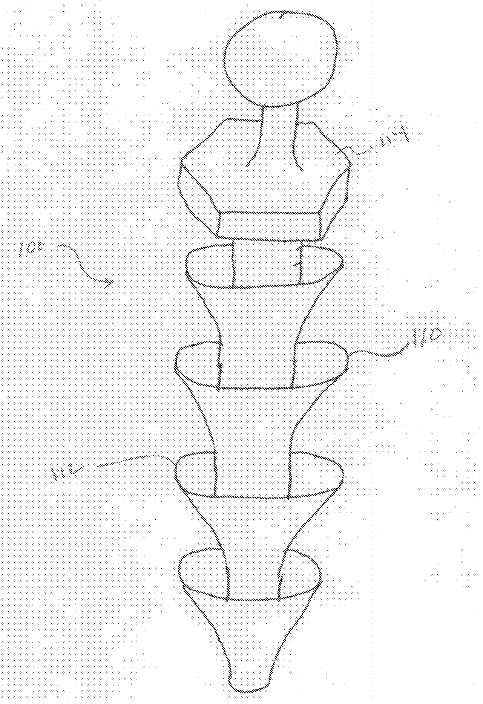
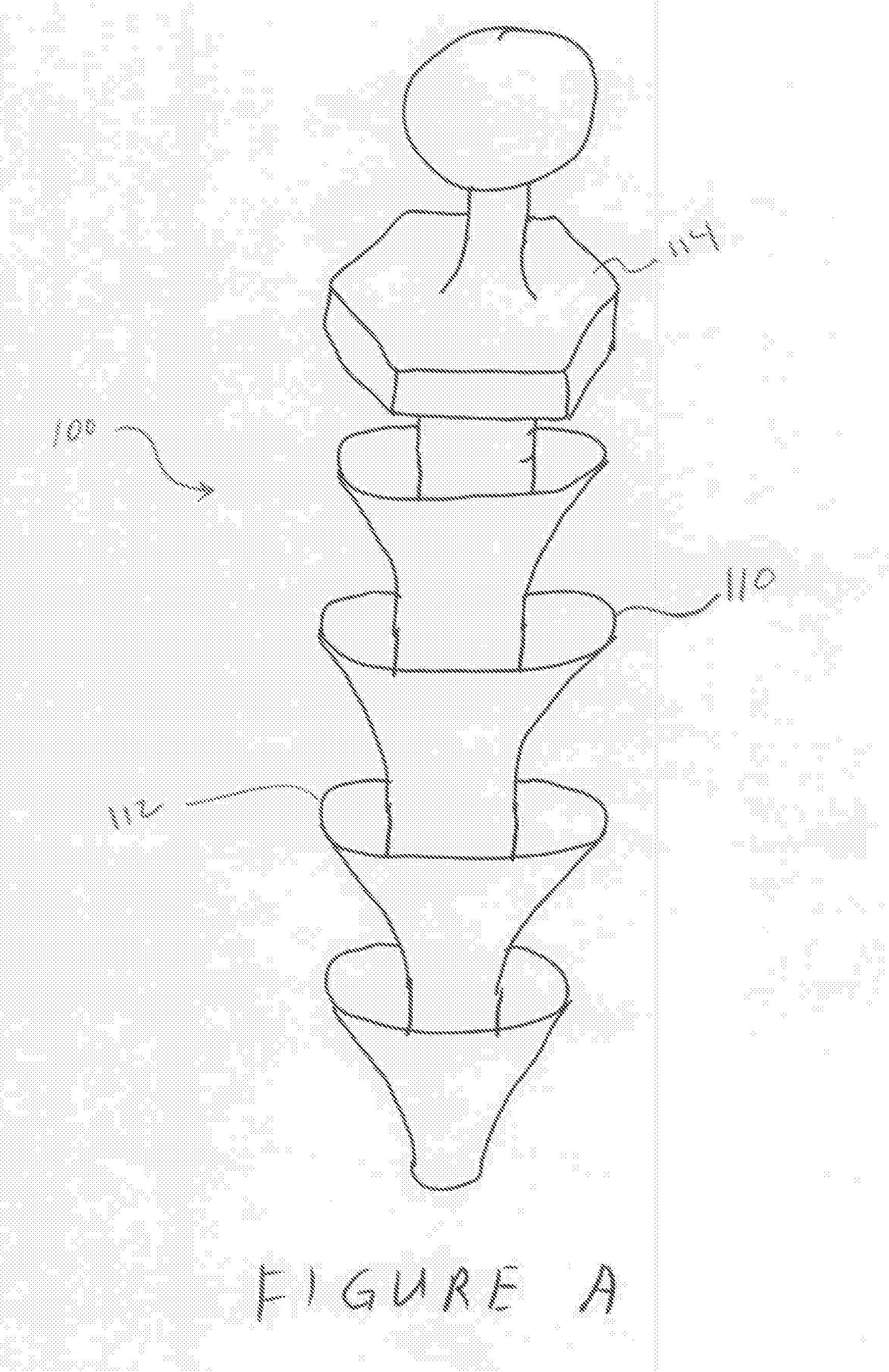
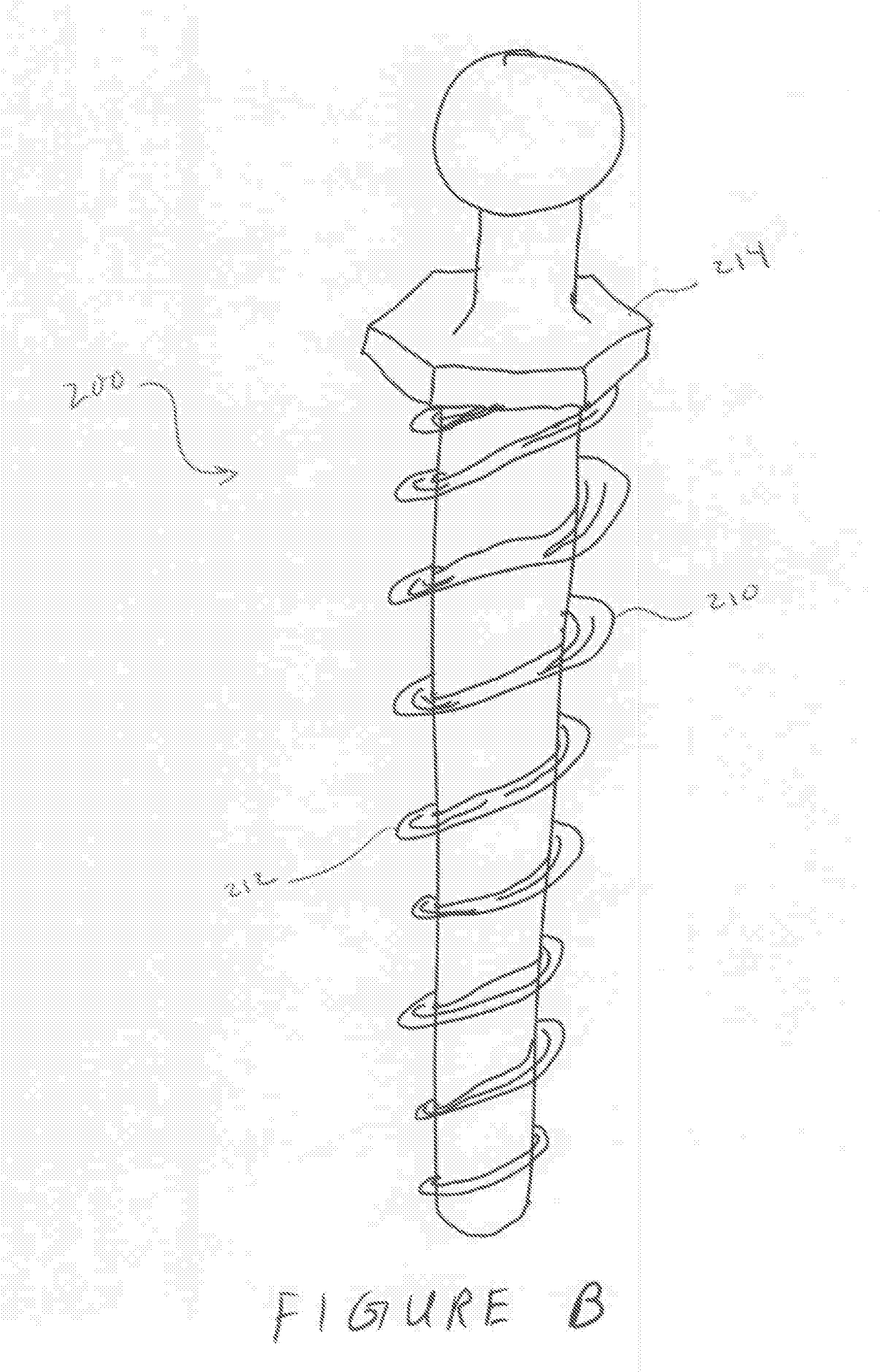
[0018]With reference now to the drawings, the preferred embodiment of the polymeric dental implants is herein described. Plastics have an ability to be strong and deform without fracturing under stress. This inherent ability of some polymers to deform (flex / stretch) instead of fracturing is ideal for both an implant post and prosthetic. Plastics that are too brittle can be modified by plasticizers to impart more elasticity to the polymer in order to make them useful as an ideal implant material. Usable plastics can be a thermoplastic or a thermoset plastic. These polymers can be comprised of straight chain, co-polymeric, block or any combination of polymers incorporated into the same mass. Plastics can be chosen from the group of polymers such as: polyacrylates, polyamide-imide, phenolic, nylon, nitrile resins, fluoropolymers, copolyvidones (copovidones), epoxy, melamine-formaldehyde, diallyl phthalate, acetal, coumarone-indene, acrylics, acrylonitrile-butadiene-styrene, alkyds, cel...


PUM


Abstract

The present invention is a dental implant utilizing a polymeric dental post. The actual prosthetic portion of the implant may also be manufactured from a polymer. Various post designs are disclosed for setting and securing the post in a patient's jaw. Numerous polymers are disclosed and may be blended to achieve desired characteristics for both the post and prosthetic.

Description

CROSS-REFERENCE TO RELATED APPLICATIONS[0001]This application claims the benefit of U.S. provisional application Ser. No. 61 / 220,306, filed Jun. 25, 2009.TECHNICAL FIELD OF THE INVENTION[0002]The present invention relates to the field of dentistry and more particularly relates to a dental prosthetic implant utilizing a polymer post.BACKGROUND OF THE INVENTION[0003]Throughout the span of the average individual's life they may through some means lose a tooth. The loss of a tooth may come by many different means such as an accident or decay. The loss of a tooth creates a gap which, on anterior surfaces, may seem aesthetically unpleasant and on a posterior tooth the loss of a chewing surface. The loss of more than one tooth will only exacerbate these problems. Once the tooth is ultimately lost the bone surrounding the tooth begins to deteriorate to the eventual loss of the socket. This creates a number of problems in creating a compatible prosthetic that is capable of replacing a lost t...

Claims


Application Information

Patent Timeline
IPC IPC(8): A61C8/00G06F17/00
CPCA61C8/0012A61C13/0004A61C8/0075A61C8/0022A61C8/0016B33Y80/00A61C13/0003
Inventor JENSEN, STEVEN D.
Owner CAO GROUP
Why Eureka
Try Eureka