
Compensating for time varying phase changes in interferometric measurements

a phase change and interferometer technology, applied in the direction of instrumentation, measurement of structures/machines, testing of fibre optic/optical waveguide devices, etc., can solve the problems of major unsolved obstacles to successfully applying ofdr to longer fibers, optical interference interference “fringes, and the inability to measure closely located events or devices on an individual event or device level

Active Publication Date: 2010-12-23
INTUITIVE SURGICAL OPERATIONS INC
View PDF21 Cites 21 Cited by
  • Summary
  • Abstract
  • Description
  • Claims
  • Application Information

AI Technical Summary

Benefits of technology

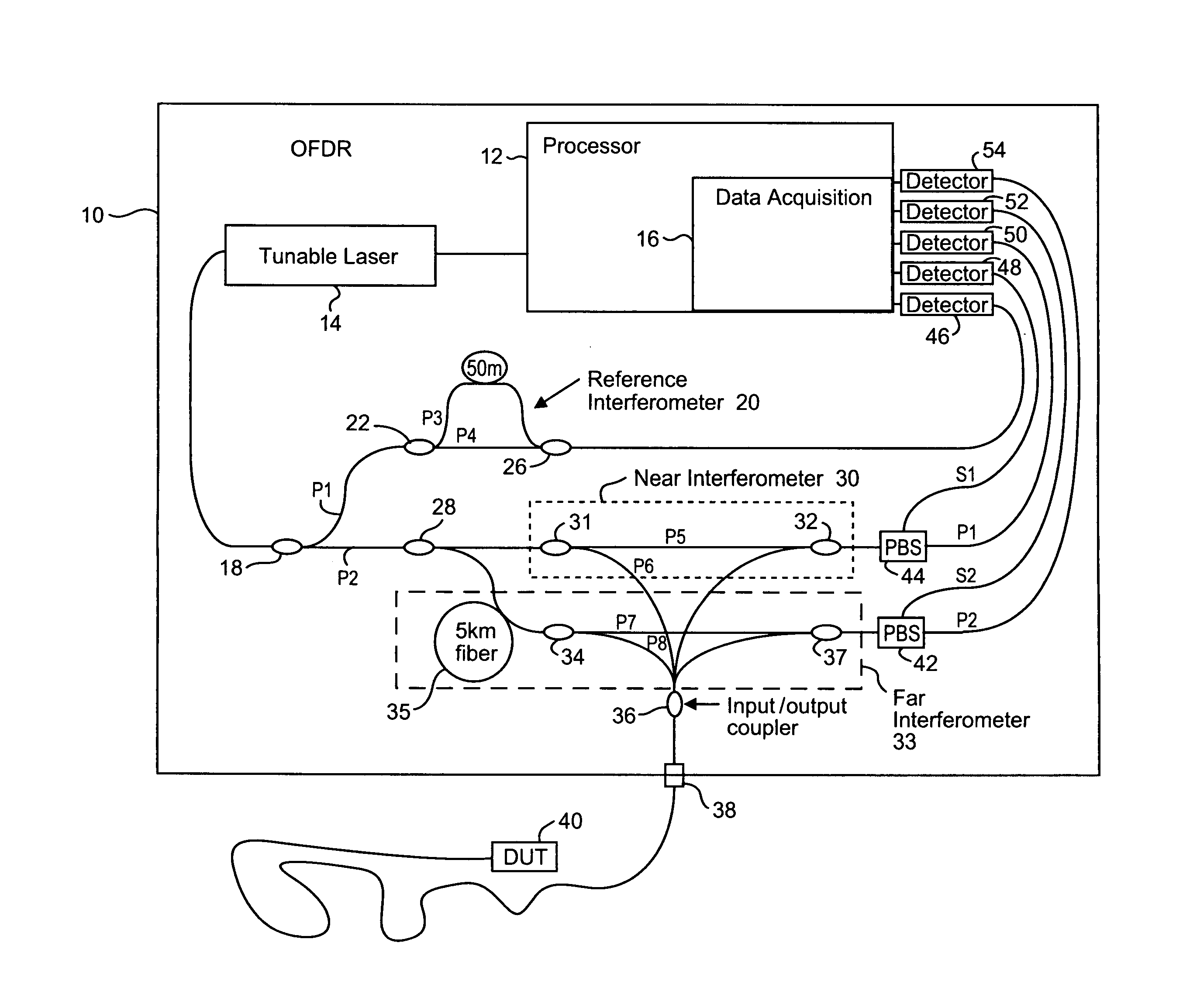
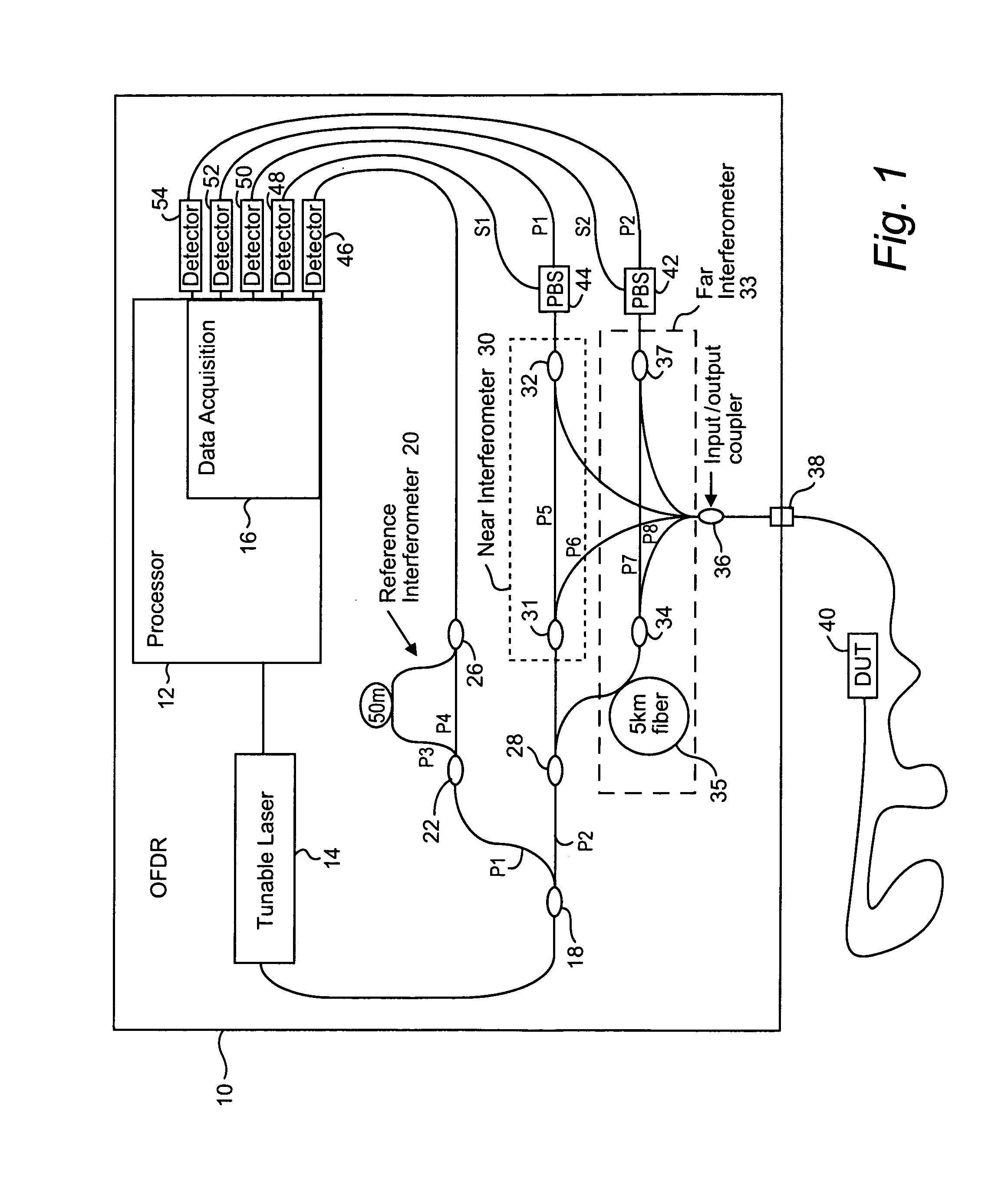
The patent text describes a method for using Optical Frequency Domain Reflectometry (OFDR) to extract information about optical devices or networks. The method involves mixing a reference signal with a reflected probe signal, and the intensity of the resulting interference signal depends on the phase and amplitude of the two signals. However, there are obstacles that can cause the phase of the interference signal to change over time, such as vibration. The patent proposes a solution to compensate for this dynamic phase change and allows for accurate measurements to be made along longer fibers. The method also allows for efficient and cost-effective storage and processing of the measured data.

Problems solved by technology

A probe signal and a reference signal originating from the same source typically mix or interfere, resulting in optical interference “fringes.” A positive fringe occurs when the light is in phase and constructively combines (interferes) to a greater intensity, and a negative fringe occurs when the light is 180 degrees out of phase and destructively combines (interferes) to cancel out the light.
Without that high resolution, measurements for closely located events or devices cannot be made on an individual event or device level.
Unfortunately, there are two major unsolved obstacles to successfully applying OFDR to longer fibers.
One source of those time-varying changes is vibration.
As a fiber vibrates, its length changes causing different time delays in the reflected light traversing those different fiber lengths.
But if the speed with which the interference pattern intensity data is detected / acquired is slower than the speed at which the phase changes, then the phase changes cannot be ignored.
There is a limit on how fast tunable lasers can be swept in terms of bandwidth, amplifier costs, increased power requirements, and processing speed.
That large amount of data is the second obstacle because there are practical constraints on how much data can be efficiently and cost effectively stored and processed.

Method used


Image

  • Compensating for time varying phase changes in interferometric measurements
  • Compensating for time varying phase changes in interferometric measurements
  • Compensating for time varying phase changes in interferometric measurements

Examples


Embodiment Construction

[0051]In the following description, for purposes of explanation and non-limitation, specific details are set forth, such as particular nodes, functional entities, techniques, protocols, standards, etc. in order to provide an understanding of the described technology. It will be apparent to one skilled in the art that other embodiments may be practiced apart from the specific details disclosed below. In other instances, detailed descriptions of well-known methods, devices, techniques, etc. are omitted so as not to obscure the description with unnecessary detail. Individual function blocks are shown in the figures. Those skilled in the art will appreciate that the functions of those blocks may be implemented using individual hardware circuits, using software programs and data in conjunction with a suitably programmed microprocessor or general purpose computer, using applications specific integrated circuitry (ASIC), field programmable gate arrays, one or more digital signal processors...


PUM


Abstract

An optical device under test (DUT) is interferometrically measured. The DUT can include one or more of an optical fiber, an optical component, or an optical system. First interference pattern data for the DUT is obtained for a first path to the DUT, and second interference pattern data for the DUT is obtained for a second somewhat longer path to the DUT. Because of that longer length, the second interference pattern data is delayed in time from the first interference pattern data. A time varying component of the DUT interference pattern data is then identified from the first and second interference pattern data. The identified time varying component is used to modify the first or the second interference pattern data to compensate for the time-varying phase caused by vibrations, etc. One or more optical characteristics of the DUT may then be determined based on the modified interference pattern data.

Description

[0001]This application is a divisional application of U.S. application Ser. No. 11 / 792,082, which is the U.S. national phase of international application PCT / US2005 / 045002 filed 13 Dec. 2005, which designated the U.S. and claims priority from U.S. Provisional Patent Application No. 60 / 635,440, filed on Dec. 14, 2004 and from U.S. Provisional Patent Application No. 60 / 659,866, filed on Mar. 10, 2005, the entire contents of each of which are incorporated by reference.RELATED PATENT APPLICATION[0002]This application is related to commonly-assigned U.S. patent application Ser. No. 11 / 062,740, filed on Feb. 23, 2005, the contents of which are incorporated by reference.TECHNICAL FIELD[0003]The technical field relates to measurement equipment and techniques, and more particularly, to improving the accuracy, precision, and application of interferometric measurements. One non-limiting example application is Optical Frequency Domain Reflectometry (OFDR).BACKGROUND AND SUMMARY[0004]Mixing betw...

Claims


Application Information

Patent Timeline
Patent Type & Authority Applications(United States)
IPC IPC(8): G01B9/02
CPCG01M11/3172G01M11/083
Inventor FROGGATT, MARKGIFFORD, DAWN K.
Owner INTUITIVE SURGICAL OPERATIONS INC
Learn More