
Cleaning blade for image-forming apparatus

Inactive Publication Date: 2010-12-16
SUMITOMO RUBBER IND LTD
View PDF2 Cites 6 Cited by
  • Summary
  • Abstract
  • Description
  • Claims
  • Application Information

AI Technical Summary

Benefits of technology

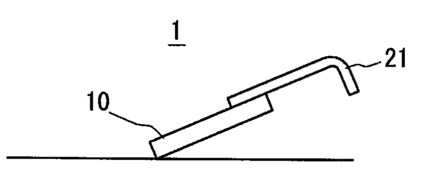
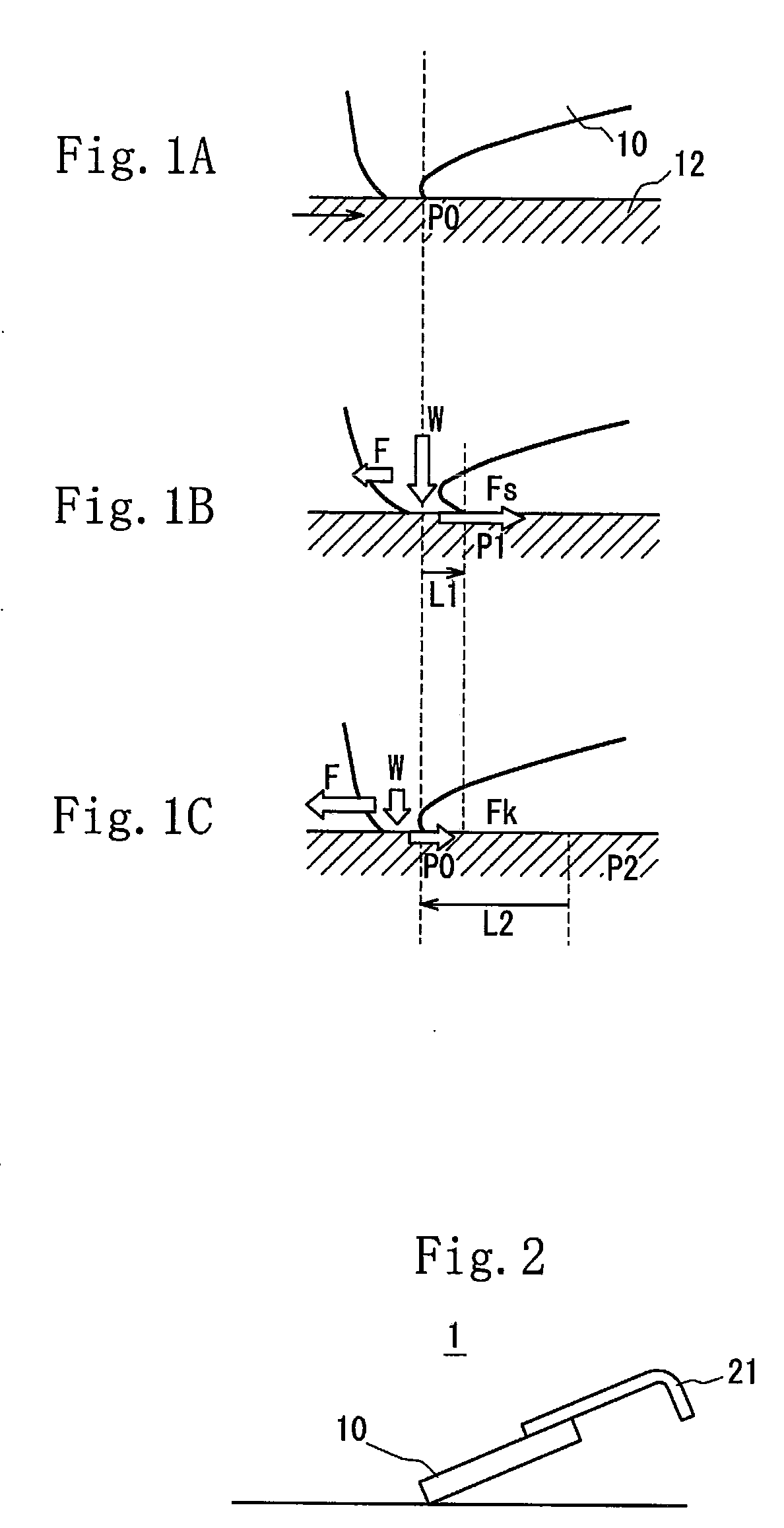
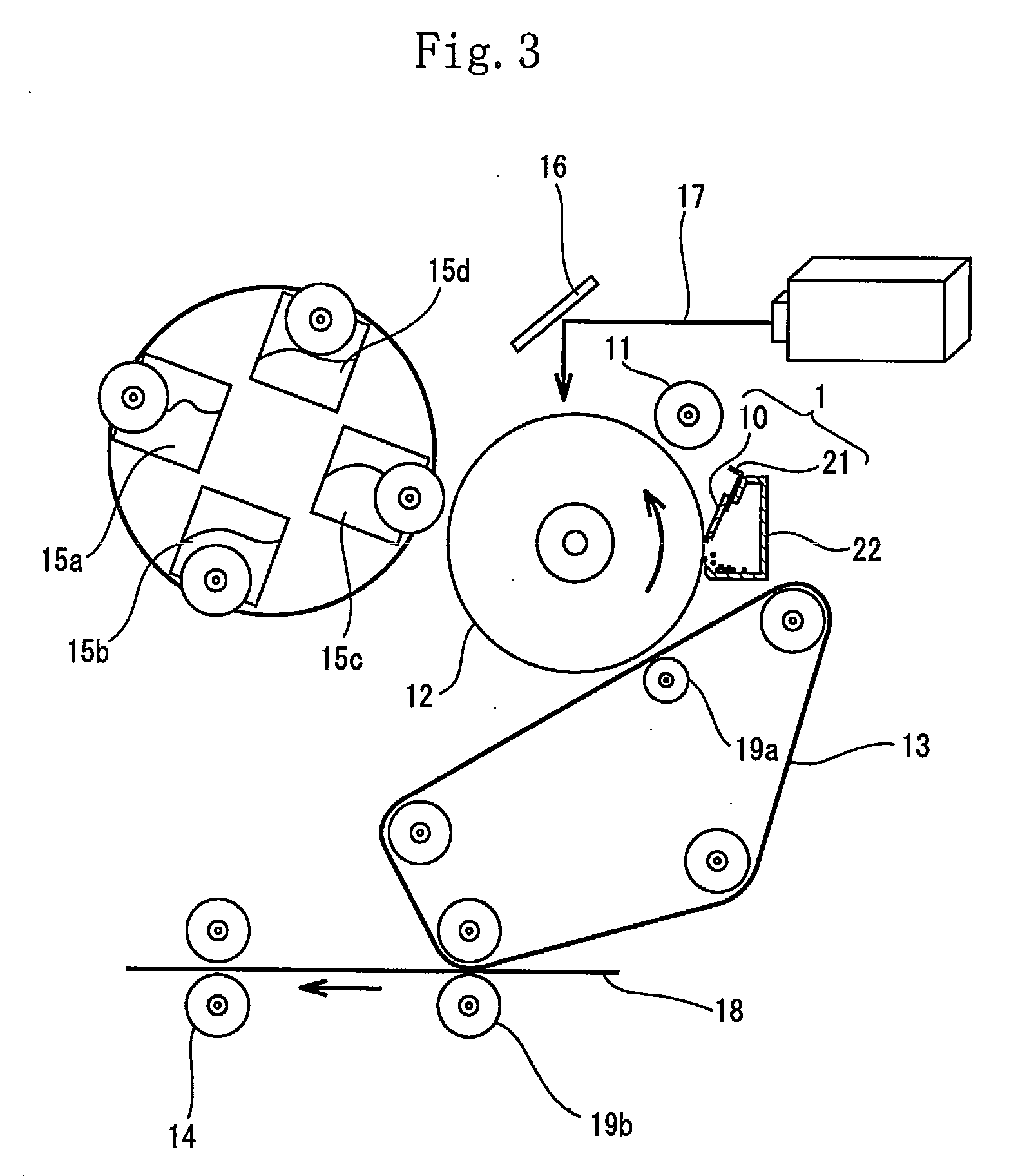
[0036]Because the cleaning blade of the present invention for the image-forming apparatus contains the rubber component consisting of any one of the HNBR, the XNBR, the HXNBR, the SBR, and the EPDM and the thermoplastic fluororesin powder having the specified particle diameter at the specified ratio, the cleaning blade has a low coefficient of static friction and a low coefficient of kinetic friction. Further it is possible to decrease the slip distance of the edge of the cleaning blade in the stick-to-slip behavior of the edge thereof. Consequently the cleaning blade is capable of displaying excellent cleaning performance.
[0037]Because the cleaning blade of the present invention for the image-forming apparatus is obtained by carrying out a normal method of molding the thermoplastic elastomer obtained by kneading the rubber component and the thermoplastic fluororesin powder, it is possible to produce the cleaning blade inexpensively and easily by utilizing existing equipment.

Problems solved by technology

The cleaning blade composed of the urethane rubber has the problem that it has a low heat resistance and that the edge thereof important in cleaning the toner wears and rounds because of the friction between it and the photoreceptor and is thus incapable of removing the toner with age.
Therefore the development of a material having a higher wear resistance than the polyurethane rubber has not been progressed.
As a result, unless the line pressure is increased, it is difficult to remove toner that remains on the surface of the photoreceptor, which causes defective cleaning to be liable to occur.
When the conventional cleaning blade composed of the polyurethane rubber is so constructed that it has a large line pressure, it has a large frictional force and thus the edge thereof wears to a high extent.
Therefore it is difficult to increase the line pressure of the cleaning blade composed of the polyurethane rubber.
The cleaning blade composed of polyurethane rubber has another problem that it generates a squeal phenomenon caused by sliding vibration at a high temperature and a high humidity.
Further because the FDLC insufficiently adheres to the polyurethane rubber, the FDLC is incapable of following the deformation of the edge.
Thus there is a possibility that the FDLC peels off the polyurethane rubber.
Therefore it is not admitted that the durability and wear resistance of the edge are sufficient in practical use.
Thus the above-described cleaning blade has a problem that the production process management is complicated and the production cost is high.
The cleaning blade having the multilayered construction has also a problem that the production cost is high and it is difficult to perform mass production.

Method used


Image

  • Cleaning blade for image-forming apparatus
  • Cleaning blade for image-forming apparatus
  • Cleaning blade for image-forming apparatus

Examples


examples 1 through 9

AND COMPARISON EXAMPLES 1 THROUGH 7

[0140]After the mixing amount of each of the rubber component, the PTFE resin powder or the ETFE resin powder both of which are the thermoplastic fluororesin powder, and the fillers shown in tables 1 and 2 was measured as shown in tables 1 and 2, the components were supplied to a rubber kneading apparatus such as a biaxial extruder, an open roll, a Banbury mixer or a kneader. Thereafter they were kneaded for five to six minutes while they were being heated to 80° C. to 120° C.

[0141]The obtained mixture and the crosslinking agent, the mixing amount of which is shown in tables 1 and 2 were supplied to the rubber kneading apparatus such as the open roll, the Banbury mixer or the kneader. Thereafter they were kneaded for five to six minutes while they were being heated to 80° C. to 90° C.

[0142]After each of obtained thermoplastic elastomers was set in a die, it was press-vulcanized at 155° C. to 175° C. for 10 to 30 minutes to obtain a sheet having a t...


PUM


Abstract

A cleaning blade for image-forming apparatuses is provided which is reduced in the coefficient of friction to attain a shortened slipping distance and thereby produce excellent cleaning performance. The cleaning blade can be easily produced at low cost. The cleaning blade for image-forming apparatus is formed from a thermoplastic elastomer comprising: a rubber ingredient comprising any one of a hydrogenerated acrylonitrile-butadiene rubber (HNBR), carboxylated acrylonitrile-butadiene rubber (XNBR), hydrogenerated carboxylated acrylonitrile-butadiene rubber (HXNBR), styrene-butadiene rubber (SBR), and ethylene / propylene / diene copolymer rubber (EPDM); and a thermoplastic fluororesin powder incorporated as the only resin powder in the rubber ingredient. The thermoplastic fluororesin powder has been incorporated in an amount of 1-80 parts by mass per 100 parts by mass of the rubber ingredient. The thermoplastic fluororesin powder has an average particle diameter of 0.1-20 um.

Description

TECHNICAL FIELD[0001]The present invention relates to a cleaning blade for use in an image-forming apparatus. More particularly, the cleaning blade is formed by molding a thermoplastic elastomer containing a rubber component and resin powder added thereto.BACKGROUND ART[0002]In an electrostatic photocopying machine, a copying operation is performed by applying an electrostatic charge to the surface of a photoreceptor by discharge, exposing an image onto the photoreceptor to form an electrostatic latent image thereon, attaching toner having an opposite polarity to the electrostatic latent image to develop the electrostatic latent image, transferring a toner image to recording paper, and heating the recording paper to which the toner image has been transferred under pressure to fix the toner to the recording paper. Therefore to sequentially copy the image of an original document on a plurality of sheets of the recording paper, it is necessary to remove the toner which remains on the s...

Claims


Application Information

Patent Timeline
IPC IPC(8): G03G21/00
CPCG03G2215/0177G03G21/0017
Inventor SUGIMOTO, MUTSUKI
Owner SUMITOMO RUBBER IND LTD
Learn More