Radiographic image display apparatus, and its method and computer program product

a technology of radiographic image and display apparatus, which is applied in the field of radiographic image display apparatus, method and computer program product, can solve the problem that the position of the pathological examination cannot be specified in the cas

Inactive Publication Date: 2010-12-02
FUJIFILM CORP
View PDF10 Cites 20 Cited by
  • Summary
  • Abstract
  • Description
  • Claims
  • Application Information

AI Technical Summary

Benefits of technology

[0011]That is, the radiographic image display apparatus is configured such that, when a radiographic image, such as a CT image and an MRI image, is displayed, on the basis of a position of a pathological examination, the position stored in association with the radiographic image, the position of the pathological examination is visibly displayed on the radiographic image, thereby enabling to accurately grasp the position of the pathological examination on the radiographic image. Note that as a method for visibly displaying a position of a pathological examination, it is conceivable to display a marker at the position of the pathological examination on the radiographic image, or to change the density or color of the pathological range corresponding to the position of the pathological examination.
[0021]According to an eighth aspect of the presently disclosed subject matter, in the radiographic image display apparatus which is applied to a pathological examination performed in such a manner that the distal end of a bronchoscope is inserted to reach a desired position of the bronchus, a sterile physiological saline solution is injected into a lung segment distal to the insertion position the injected solution is sucked back, and cells, protein, and microorganisms in the sucked back saline solution are examined, the display control device includes a recognizing device which, when the distal end position of the bronchoscope inserted into the bronchus, or one of a name and a symbol that indicate the anatomical site corresponding to the distal end position of the bronchoscope is inputted by the position specifying device, recognizes, from the radiographic image, a dominated area of the bronchus which is distal to the distal end position of the bronchoscope, and the display control device makes the display device visually display the recognized dominated area of the bronchus in a manner that the recognized dominated area of the bronchus can be discriminated from the other regions on the radiographic image displayed by the display device.
[0022]According to a ninth aspect of the presently disclosed subject matter, the radiographic image display apparatus according to one of the first to eighth aspects, further includes: a pathology database which manages information on a pathological examination of a tissue collected from a position of the pathological examination, and the display control device makes the display device visibly display the position of the pathological examination on the radiographic image displayed by the display device and reads the information of the corresponding pathological examination from the pathology database to make the display device display the read information. This makes it possible to clearly grasp the correspondence relationship between the image at the position of the pathological examination (biopsy site) on the radiographic image and the information on the pathological examination. Note that the information on the pathological examination is information including at least one of a pathology image, such as a microphotograph of the collected tissue, and a pathology report.
[0034]According to the presently disclosed subject matter, it becomes possible that a position of a pathological examination is stored in association with a radiographic image, such as a CT image and an MRI image, and when the radiographic image is displayed, the position of the pathological examination is visibly displayed on the radiographic image on the basis of the position of the pathological examination stored in association with the radiographic image. Thus, the position of the pathological examination can be accurately grasped on the radiographic image.
[0035]Further, it becomes possible that information (a pathology image and a pathology report) on the pathological examination of a tissue collected from the position of the pathological examination is displayed simultaneously with the radiographic image. This enables to clearly grasp a correspondence relationship between the image at the position of the pathological examination (biopsy site) on the radiographic image and the information on the pathological examination.

Problems solved by technology

Thus, there is a problem that since the site of a pathological examination cannot be accurately specified on a CT (Computed Tomography) image or an MRI (Magnetic Resonance Imaging) image, the position of the pathological examination cannot be specified in the case where there are different observations in the site area.

Method used


Image

  • Radiographic image display apparatus, and its method and computer program product
  • Radiographic image display apparatus, and its method and computer program product
  • Radiographic image display apparatus, and its method and computer program product

Examples


first embodiment

[0052]In the following, a first embodiment according to the presently disclosed subject matter will be described with reference to FIG. 2 to FIG. 6.

[Registration System]

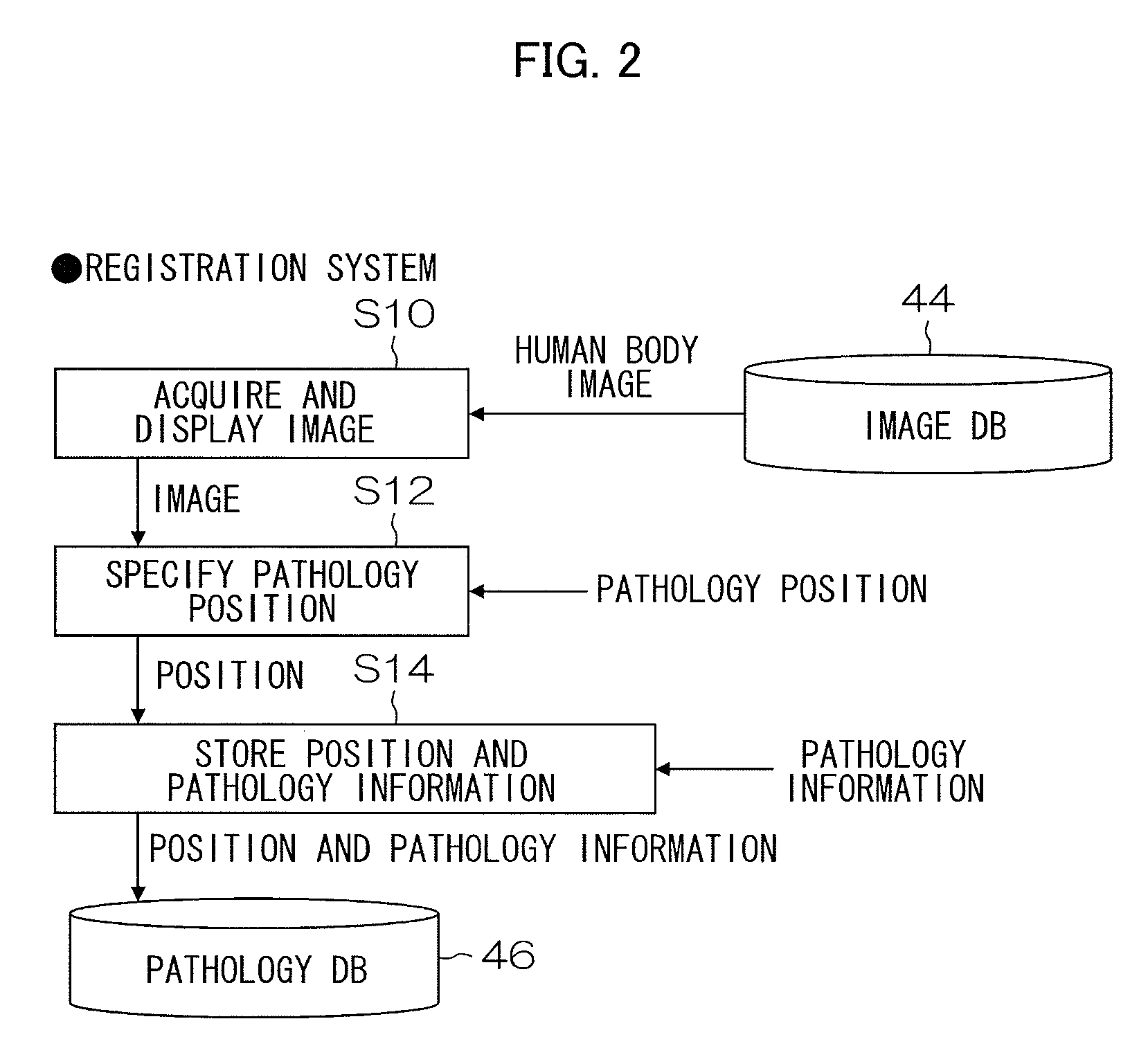
[0053]FIG. 2 is a flow chart showing a processing procedure for registering a position, and the like, of a pathological examination on a radiographic image in the pathology DB 46 by the radiographic image display apparatus 10 according to a first embodiment.

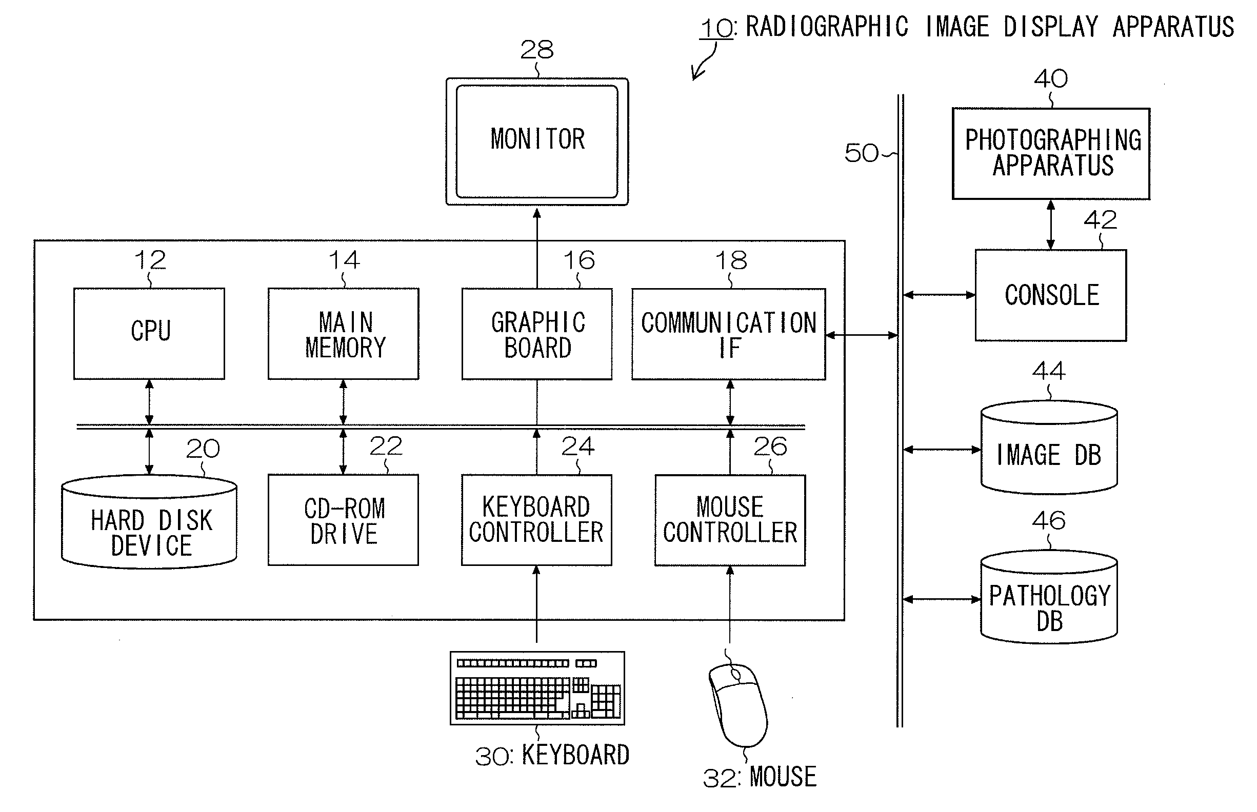
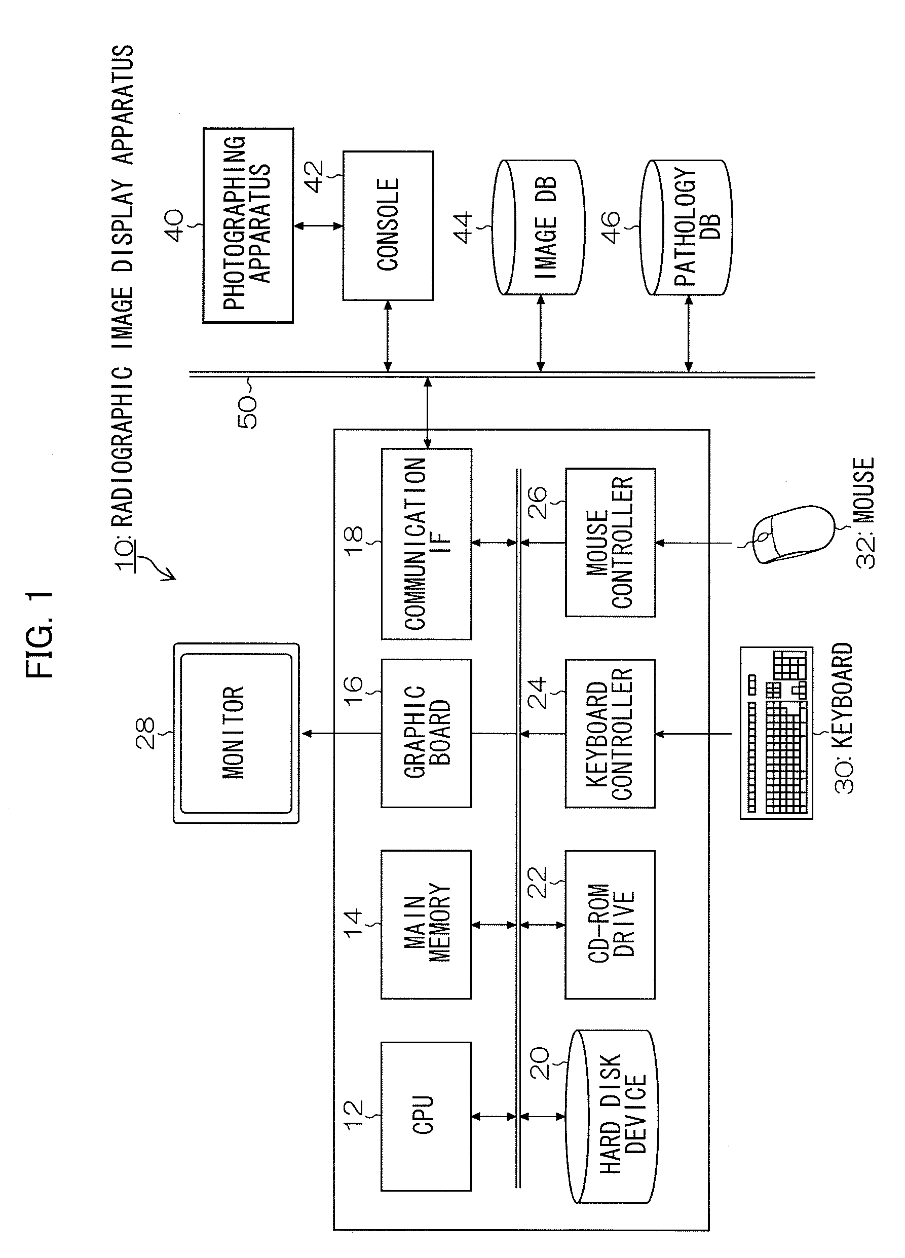
[0054]The CPU 12 executes a radiographic image display program according to an input operation by the keyboard 30 and the mouse 32, to function as an image acquiring device which acquires a desired radiographic image (hereinafter referred to as “human body image”) from the image DB 44 via the network 50 and the communication I / F 18, and makes the monitor device 28 display the acquired human body image via the graphic board 16 (step S10). Note that a file (DICOM file) based on the DICOM (Digital Imaging and Communications in Medicine) standard can be considered as ...

second embodiment

[0074]Next, a second embodiment according to the presently disclosed subject matter will be described with reference to FIG. 7 and FIG. 8.

[Registration System]

[0075]FIG. 7 is a flow chart of showing a processing procedure for registering a position, and the like, of a pathological examination on a radiographic image in the pathology DB 46 by the radiographic image display apparatus 10 according to a second embodiment. Note that the steps of the flow chart of the second embodiment that are common to the steps of the flow chart of the first embodiment shown in FIG. 2 are designated by the same step numbers, and the detailed description thereof is omitted.

[0076]The first embodiment is configured such that a marker indicating a position of a pathological examination (biopsy site) at which position the biopsy was performed is displayed on a human body image including the position of the pathological examination. However, the second embodiment is different from the first embodiment in tha...

third embodiment

[0092]Next, a third embodiment according to the presently disclosed subject matter will be described with reference to FIG. 9 to FIG. 11.

[Registration System]

[0093]FIG. 9 is a flow chart showing a processing procedure for registering a position, and the like, of a pathological examination on a radiographic image in the pathology DB 46 by the radiographic image display apparatus 10 according to a third embodiment. Note that the steps of the flow chart of the third embodiment that are common to the steps of the flow chart of the first embodiment shown in FIG. 2 are designated by the same step numbers, and the detailed description thereof is omitted.

[0094]The third embodiment corresponds, for example, to the case where when bronchial alveolar lavage (BAL) is performed, and the method for specifying the position of the pathological examination (biopsy site) is different from those in the first and second embodiments.

[0095]The BAL means a method in which the distal end of a bronchoscope ...


PUM


Abstract

A position of a pathological examination on a radiographic image, such as a CT image and an MRI image, is stored beforehand in association with the radiographic image. When the radiographic image is displayed on a monitor device, a marker indicating the position of the pathological examination, which is stored in association with the human body image, is displayed at a corresponding position on the radiographic image displayed on the monitor device. Further, information (a pathology image and a pathology report) on the pathological examination of a tissue collected from the position of the pathological examination is displayed simultaneously with the radiographic image. Therefore, the position of the pathological examination can be accurately grasped on the radiographic image, and the correspondence relationship between the image at the position (biopsy site) of the pathological examination on the radiographic image, and the information on the pathological examination can be clearly grasped.

Description

CROSS-REFERENCE TO RELATED APPLICATIONS[0001]This application claims the priority benefit under 35 U.S.C. §119 of Japanese Patent Application No. 2009-129014 filed on May 28, 2009, which is hereby incorporated in its entirety by reference.BACKGROUND OF THE INVENTION[0002]1. Field of the Invention[0003]The presently disclosed subject matter relates to a radiographic image display apparatus, and method and computer program product, and more particularly to a technique used to display a medical radiographic image relating to pathological examination.[0004]2. Description of the Related Art[0005]Conventionally, when a pathological examination is performed, an anatomical site name is written in a pathological examination report, and a biopsy position is specified on a radiographic image on the basis of the site name.[0006]Further, a medical image diagnostic apparatus is proposed, in which, when a predetermined coordinate position, such as a position of a lung nodule, is set in a three-dim...

Claims


Application Information

Patent Timeline
Patent Type & Authority Applications(United States)
IPC IPC(8): G06K9/00A61B5/055A61B6/03G16H30/20G16H30/40
CPCG16H40/63G06F19/321G16H30/40G16H30/20
Inventor MORIYA, YOSHIYUKI
Owner FUJIFILM CORP
Why Eureka
Try Eureka