
Capacitor based bi-directional degaussing device with chamber

a bi-directional degaussing and capacitor technology, applied in the field of magnetic recording media erasers, can solve the problems of uneconomical repair, inability for an unauthorized person to read such materials, and inability to reduce the noise of certain memory media, so as to reduce the noise of media at the deep level, and reduce the effect of magnetic field leakag

Active Publication Date: 2010-12-02
PROTON DATA SECURITY LLC
View PDF20 Cites 32 Cited by
  • Summary
  • Abstract
  • Description
  • Claims
  • Application Information

AI Technical Summary

Benefits of technology

[0015]The device includes a chamber and the use of chamber enclosure covers that focus the magnetic flux and further reduce and / or eliminate magnetic field leakage.
[0016]Another objective of the invention is to provide an apparatus capable of deep level degaussing reduction of media noise.

Problems solved by technology

Should the storage medium be discarded, the ability for an unauthorized person to read such materials could be most damaging.
While most computers could be repaired when they fail, technological advances and the low cost of replacement has made such repair uneconomical and most computers are simply discarded should a failure occur.
Unfortunately, the finding of discarded electronic storage media still containing data is now common news.
While certain memory media may be easily destroyed, like optical memory, hard drives with rotating memory storage disks may be more difficult to degauss due to the housing structure.
The prior art systems using permanent magnets may not address the problems associated with degaussing of the newer type of hard drive components that are not readily accessible, due to such factors as the sealing of the hard drive disk and / or head within an enclosure having high coercivity magnetic media.
Thus, what is lacking in the art is a degaussing apparatus capable of housing a magnetic disc for subject to a capacitor based bi-directional degaussing current, the housing acting as a reflective chamber and allowing a pass through of the storage medium.

Method used


Image

  • Capacitor based bi-directional degaussing device with chamber
  • Capacitor based bi-directional degaussing device with chamber
  • Capacitor based bi-directional degaussing device with chamber

Examples


Embodiment Construction

[0031]While the present invention is susceptible of embodiment in various forms, there is shown in the drawings and will hereinafter be described the presently preferred embodiment with the understanding that the present disclosure is to be considered an exemplification of the invention and is not intended to limit the invention to the specific embodiments illustrated.

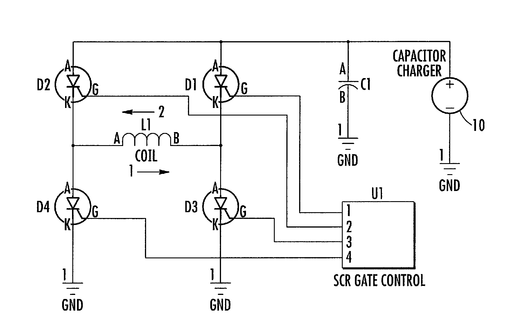
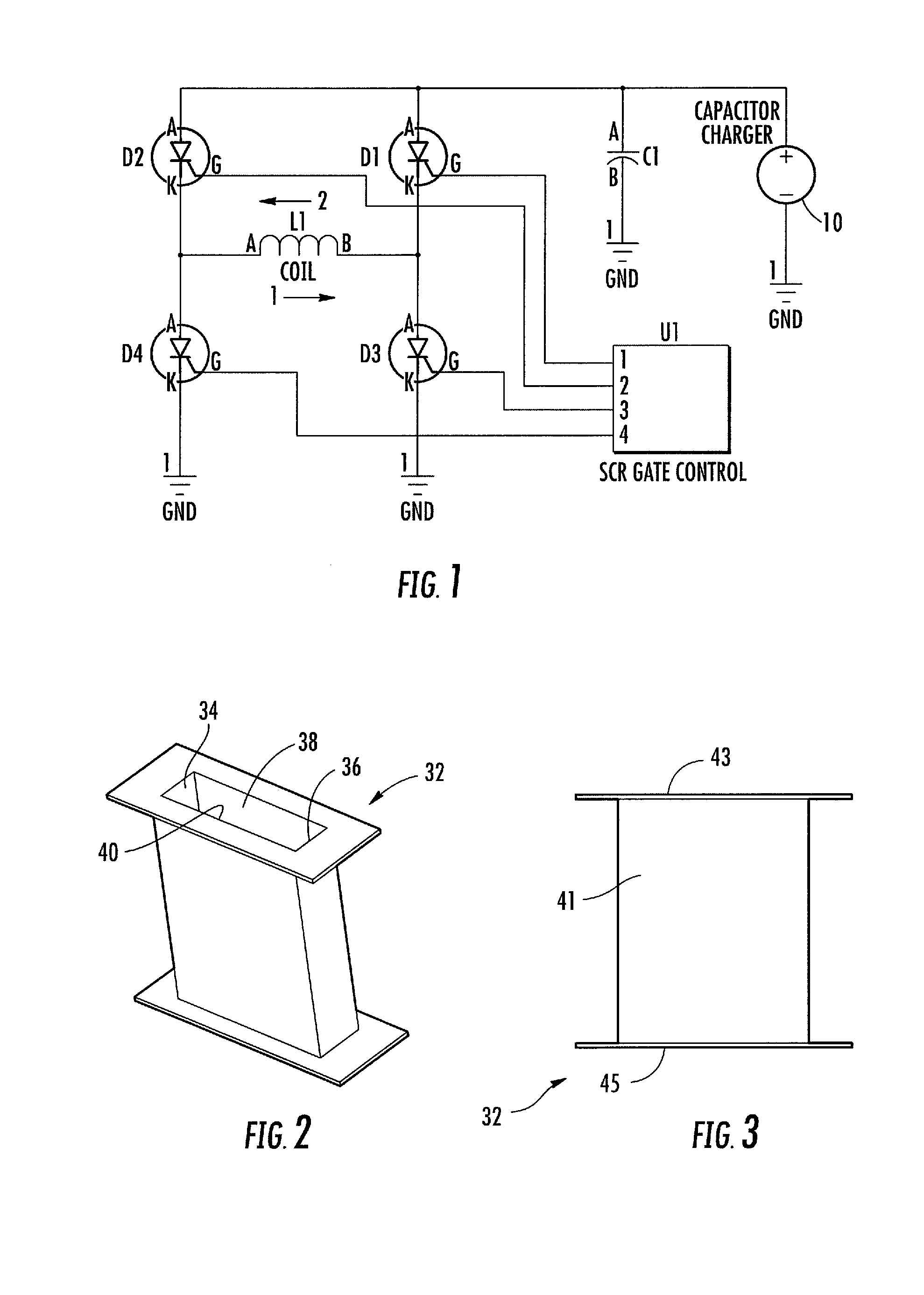
[0032]Now referring to FIG. 1, set forth is a control circuit of the preferred invention. A control circuit has a capacitor charger 10 for reduction of power, preferably 120 VAC to DC, the charge capable of providing a charge to a capacitor bank C1 of about 400 VDC. Operation of the capacitor is controlled by SCR thyristor gate controller U1. Upon the capacitor bank C1 being fully charged, SCR'z Diode 2 and Diode 3 are fired by the gate controller U1. The firing of the gate controller causes capacitor bank C1 to discharge through coil L1 with the polarity flowing in the direction from A to B as shown by the numeral 1. ...


PUM


Abstract

Disclosed is an apparatus for destroying electronic memory media by use of a bi-directional degaussing device. The degaussing device utilizes an SCR gate controller to cause bi-directional polarity from a charged capacitor into a sealed chamber containing the magnetic media. The chamber has a movable steel plate cover and floor that encloses the chamber containing magnetic media during the degaussing stage. The cover and floor cause a reflective chamber that focuses and directs the flux level to the magnetic media. The gate controller allows the use of the same capacitor bank to power a coil in two different directions to obtain effective degaussing without multiple coils or directional capacitors.

Description

FIELD OF INVENTION[0001]The invention relates to magnetic recording media erasers and, in particular, to a capacitor based bi-directional degaussing apparatus capable of erasing electronic memory media placed within a shielded chamber.BACKGROUND OF THE INVENTION[0002]Electronic storage of media is currently the preferred method of storing information. From non-essential phone numbers to top level government security information, magnetic media has been found to be secure as long as the magnetism of the storage medium is protected. For this reason the reliance upon magnetic storage mediums for storing all types of information is increasing exponentially. Should the storage medium be discarded, the ability for an unauthorized person to read such materials could be most damaging. Thus, the need to erase information from the storage medium has become of paramount importance.[0003]While most computers could be repaired when they fail, technological advances and the low cost of replacemen...

Claims


Application Information

Patent Timeline
IPC IPC(8): H01F13/00
CPCG11B5/0245H01F13/006
Inventor OLLIGES, WILLIAM E.
Owner PROTON DATA SECURITY LLC
Learn More