
Blade member, and edge working apparatus for the blade member

a blade member and blade technology, applied in the field of blade members, can solve the problems of reducing the sharpness of the edge and degrading the cutting quality, and achieve the effects of improving rigidity, hardness of the edge, and enhancing rigidity

Active Publication Date: 2010-11-18
KAI R&D CENT CO LTD +1
View PDF5 Cites 6 Cited by
  • Summary
  • Abstract
  • Description
  • Claims
  • Application Information

AI Technical Summary

Benefits of technology

[0004]According to the technique disclosed in Patent Document 1, a cutting blade is subjected to ion implantation to improve the hardness. According to the technique disclosed in Patent Document 2, an edge is subjected to reactive-ion etching to increase the sharpness.
[0005]Accordingly, it is an objective of the present invention to provide a blade member having a superior edge by improving the processing techniques of ion beam treatment and plasma ion implantation, and a working apparatus capable of efficiently working such edges.
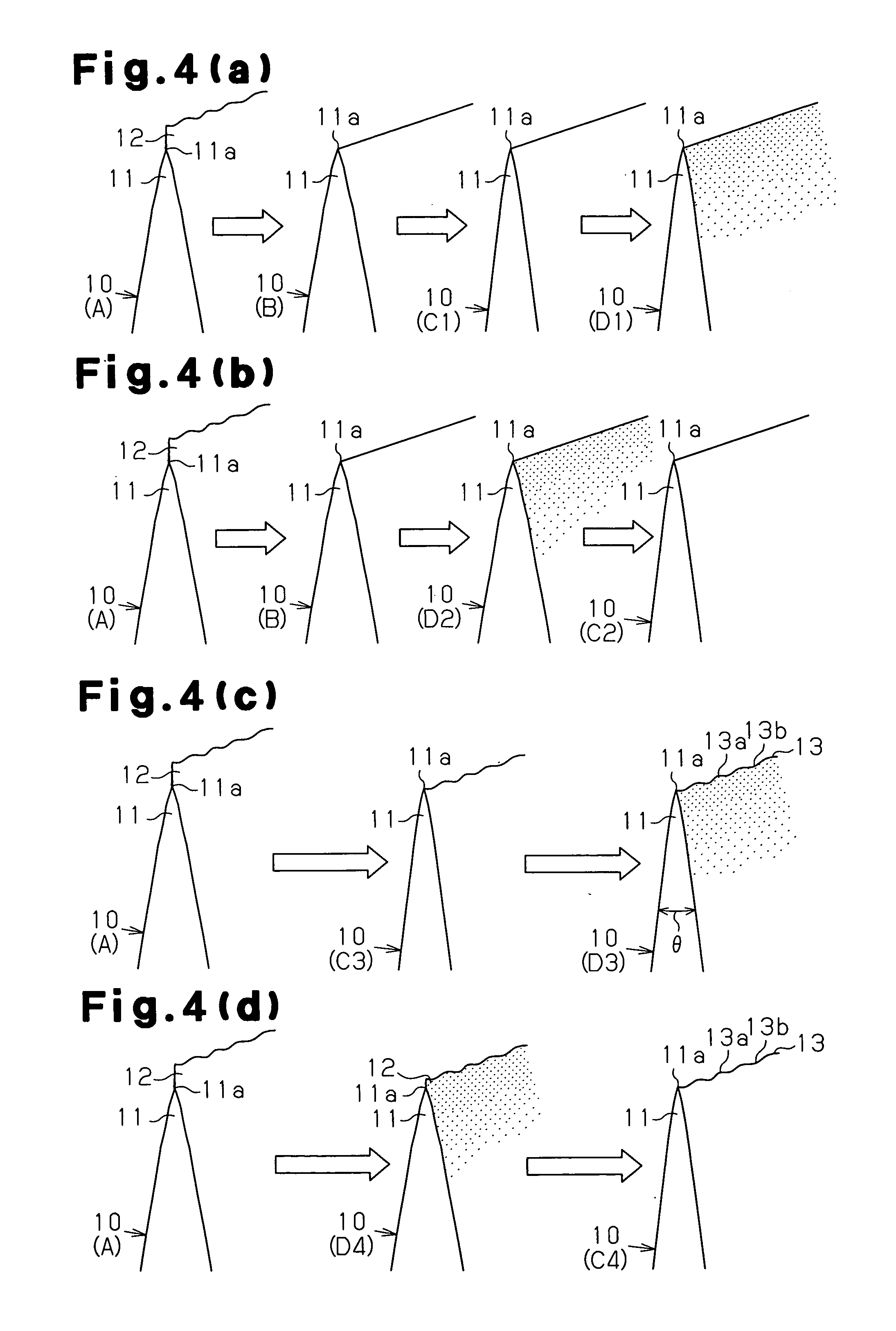
[0006]In accordance with a first aspect of the present invention, a blade member is provided in which edges of a group of blades are subjected to ion beam treatment using a plasma ion gun in a vacuum chamber, in which argon is used as a medium. The pressure of the argon gas is 0.1 to 1 Pa, a bias voltage applied to the blade group is 0.1 to 1000 V, and the processing time is 5 to 300 minutes. This increases the sharpness of the edge, so that the cutting quality is enhanced.

Problems solved by technology

This reduces the sharpness of the edge and degrades the cutting quality.

Method used


Image

  • Blade member, and edge working apparatus for the blade member
  • Blade member, and edge working apparatus for the blade member
  • Blade member, and edge working apparatus for the blade member

Examples


Embodiment Construction

[0023]One embodiment of the present invention will now be described with reference to the drawings.

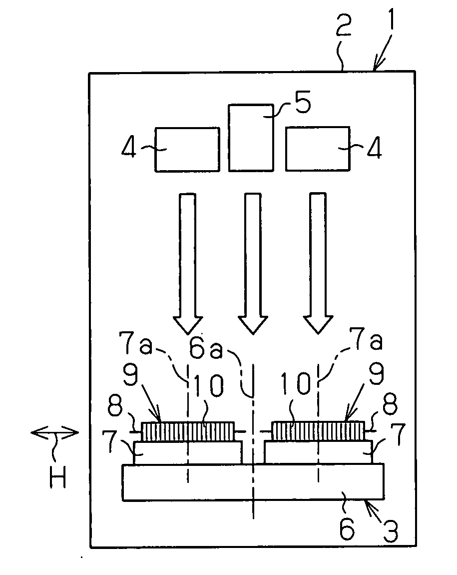
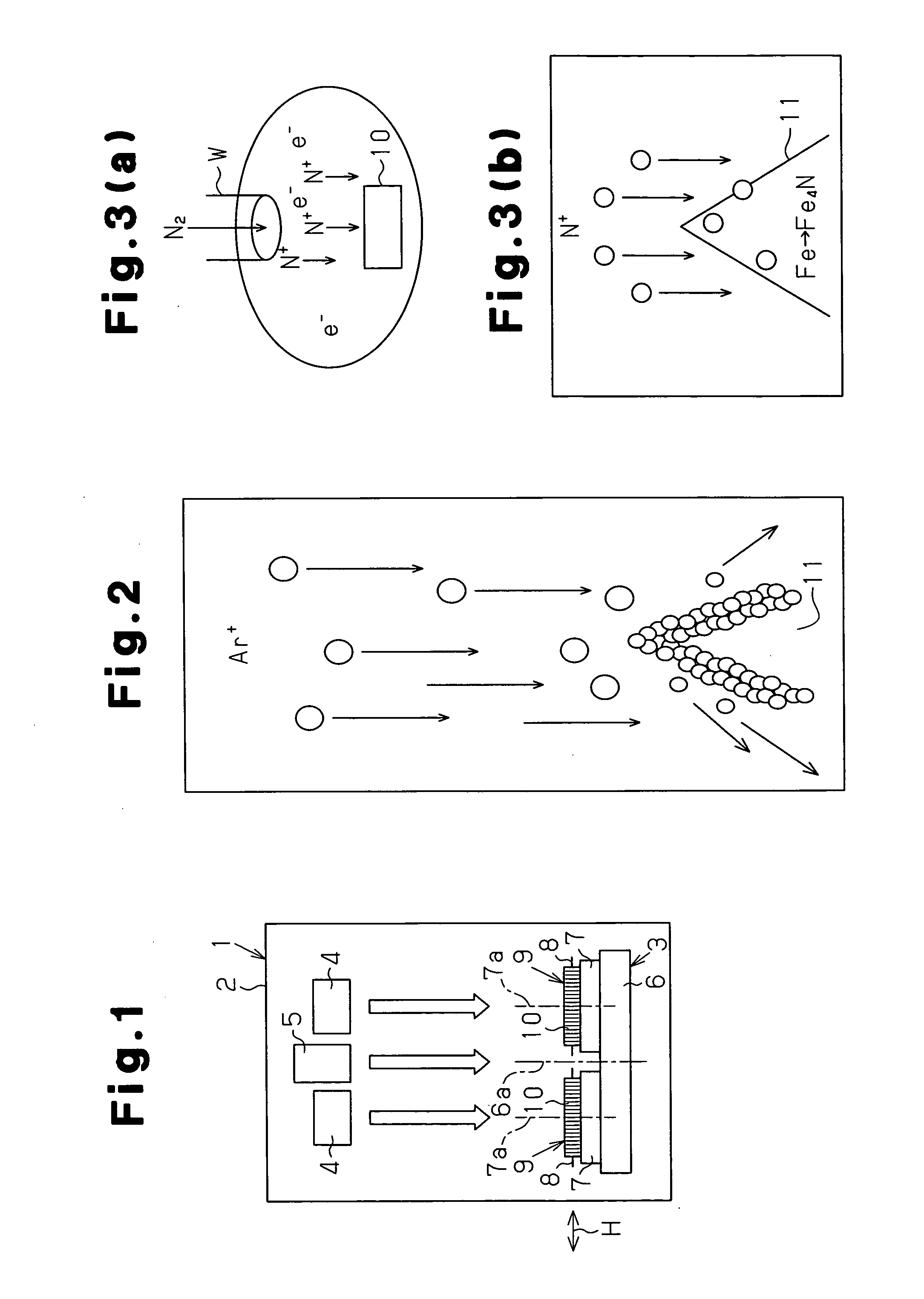
[0024]FIG. 1 schematically shows a working apparatus 1, which has a vacuum chamber 2. A blade mounting stage 3 is provided in a lower portion of the vacuum chamber 2. In an upper portion of the vacuum chamber 2, plasma ion guns 4 and a plasma ion implantation gun 5 are arranged in parallel. Each plasma ion gun 4 performs ion beam treatment using argon as medium, while the plasma ion implantation gun 5 performs plasma ion implantation using nitrogen plasma. An orbit base 6 is supported by the blade mounting stage 3. The orbit base 6 functions as a rotating body that rotates about an orbital axis 6a. Spinning bases 7 are supported on the orbit base 6. Each spinning base 7 functions as a rotating body that spins about a rotational axis 7a. A group of blades 9 is attached to each spinning base 7, so as to be located about the orbital axis 6a. The blade group 9 includes a plurality of blade...


PUM

PropertyMeasurementUnit
pressureaaaaaaaaaa
heightaaaaaaaaaa
edge angleaaaaaaaaaa

Abstract

In a vacuum chamber, the edge of each blade group is subjected to an ion beam treatment under predetermined conditions using a plasma ion gun and argon as a medium, and is subjected to a plasma ion implantation of nitrogen plasma under predetermined conditions using a plasma ion implantation gun. As a result, it is possible to provide a blade member having an edge of a cutting quality enhanced by increasing the sharpness, a blade member having an edge of a rigidity enhanced by increasing the hardness, and a working apparatus capable of working those edges efficiently.

Description

CROSS REFERENCE TO RELATED APPLICATIONS[0001]This application is a U.S. national stage application of PCT / JP2008 / 073494 filed on Dec. 24, 2008, and claims priority to, and incorporates by reference, Japanese Patent Application No. 2007-337779 filed on Dec. 27, 2007.FIELD OF THE INVENTION[0002]The present invention relates to a blade member used, for example, in a razor, and an apparatus for working the edge of the blade member.BACKGROUND OF THE INVENTION[0003]Conventionally, the edge of this type of blade member is worked with a razor strop to remove burrs. This reduces the sharpness of the edge and degrades the cutting quality. Also, the hardness and rigidity of the edge are reduced.Patent Document 1: Japanese Examined Patent Publication No. 54-28379Patent Document 2: Japanese Laid-Open Patent Publication No. 2007-61212DISCLOSURE OF THE INVENTION[0004]According to the technique disclosed in Patent Document 1, a cutting blade is subjected to ion implantation to improve the hardness....

Claims


Application Information

Patent Timeline
Patent Type & Authority Applications(United States)
IPC IPC(8): B26D1/00H01J37/317H01J37/20
CPCB26B21/54B26B9/00C23F4/00Y10T83/929
Inventor UEMURA, KENSUKEOHTSUBO, HIROSHI
Owner KAI R&D CENT CO LTD
Learn More