
Method and device for rotational marking

a technology of rotational marking and markings, applied in the direction of recording equipment, electrodes and associated parts, printing, etc., to achieve the effect of facilitating the insertion and extraction of the electrod

Active Publication Date: 2010-11-11
ON LASER SYST & APPL
View PDF3 Cites 12 Cited by
  • Summary
  • Abstract
  • Description
  • Claims
  • Application Information

AI Technical Summary

Benefits of technology

[0024]The objective of this invention is to solve the problems mentioned above, developing a method and an arrangement for rotational marking of cylindrical elements by means of a laser radiation that allows the processing of these cylindrical elements rotating at a variable speed with the advantages listed below.
[0026]In addition, this configuration avoids having to stop the marking process to change marking plates. Being a process with electronic control, it allows changing the marking pattern between a stopper and the next, without having to stop the process.

Problems solved by technology

Also, in the case of natural cork stoppers substitutes, using synthetic materials such as polypropylene, thermoplastic foam or silicone, the process of marking is done by offset printing, tampography, thermal transfer, using special inks and drying methods to help fixing the ink to these materials, with great difficulty due to non-absorption of the material.
Another drawback of the cork marking process using stamps, is that the cork stopper processing company is forced to store each one of the marking plate sets, requiring large storage space in the production facilities as the years go by.
It is also true that these marking plates require maintenance, repair and replacement in many cases for other new marking plates, because by using them they become completely or partially damaged.
At present and at the end of the process, stoppers do not usually incorporate any information related to these batches called “washing batches.” Therefore, if the winery finds, within the entire order, a sole stopper without the appropriate chemical treatment (as an example—too much paraffin, poor color matching, etc..), the winery for security tends to return the whole order to the cork processing company, which can involve batches up to 100,000 with the inconvenience that this may represent.
This division included on the marking pattern represents a big problem for the current systems, since it involves an ongoing marking plate change or changing some parts of the marking plate, as if it was a numbering revolver that changes numbers.
Usually this process is manual and limited to a few numbers / letters and requires stopping the marking process to clean and substitute the marking plates with the numbers to change.
On the other side, even though this ink marking method since its introduction years ago reached a greater image resolution for wineries in their marking on the stoppers, bringing to these marking patterns drawings of castles, profiles of the winery and its landscape, grounds flowers, etc., compared with the markings of the stoppers obtained previously with the old hot marking plates / metal stamps previously used for marking by heat and pressure, it is noteworthy that the process still includes serious and annoying inconveniences associated with the ink marking, and especially in low-porous materials such as cork and that the cork industry needs to improve.
Some of the drawbacks associated with ink marking stoppers are: 1) The difficulty in performing marking patterns whose images / logos have large areas that should be marked, resulting in a cluttered image by excess of ink; 2) the need to let the cork stoppers dry for about 24 hours after being marked with ink, prior to the next silicone / paraffin process described; 3) using a specific ink for application in materials for the food industry, that it is being used to only mark the body of the stopper, not being allowed by the health authorities the use on the ends because sooner or later one of the ends will be in contact with the beverage contained inside the bottle in question; 4) when changing a marking plate / stamp it is required to stop the machine between 5 and 10 minutes not only to replace the marking plate, but also clean up the marking mechanism and avoid the accumulation of waste that would hinder the process and deteriorate the marking quality (it has been measured the machine's stop average time for cleaning and changing marks made by a qualified operator who oversees two ink markers, in about 1 hour a day per shift); and 5) the use of inks in food products that governments' of all countries and end users in general to eliminate to avoid risks of food contamination consumers.
Although such systems work quite well, they require high maintenance, have consumables and marking plates costs, and require high labor for such tasks as well as monitoring which represents a clear disadvantage for the industry.
To point out that the patent refers to the method of marking synthetic stoppers of that composition, that should be previously made with the right mix including the special additive, in addition to a specific type of laser for its marking, and an optical setup and focalization that are critical to achieving a proper result that does not mar the surface of the stopper, resulting in a low reliability marking process, low speed and the inability to mark the whole body of the stopper as well as their heads, a high investment and a variable cost (additive).
There is, however, an existing a serious problem that impedes the direct use in this application of any of the above mentioned, mainly because none of them is capable of generating frequency pulses above 100 kHz.
At the time that these settings were tried, the result was that the laser was not able to produce a regular marking, either was making holes, burning in-depth, or melting the material in the contact point with the laser beam, generating defects in the material to be processed, or that the maximum acceptable speed for the process was so slow that it was necessary to rule out the technique for not being able to be industrialized and require high investment.

Method used


Image

  • Method and device for rotational marking
  • Method and device for rotational marking
  • Method and device for rotational marking

Examples


Embodiment Construction

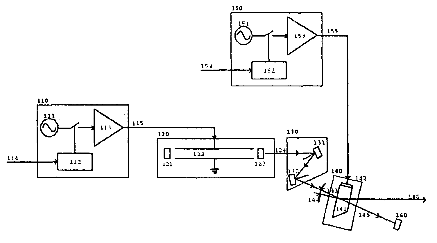
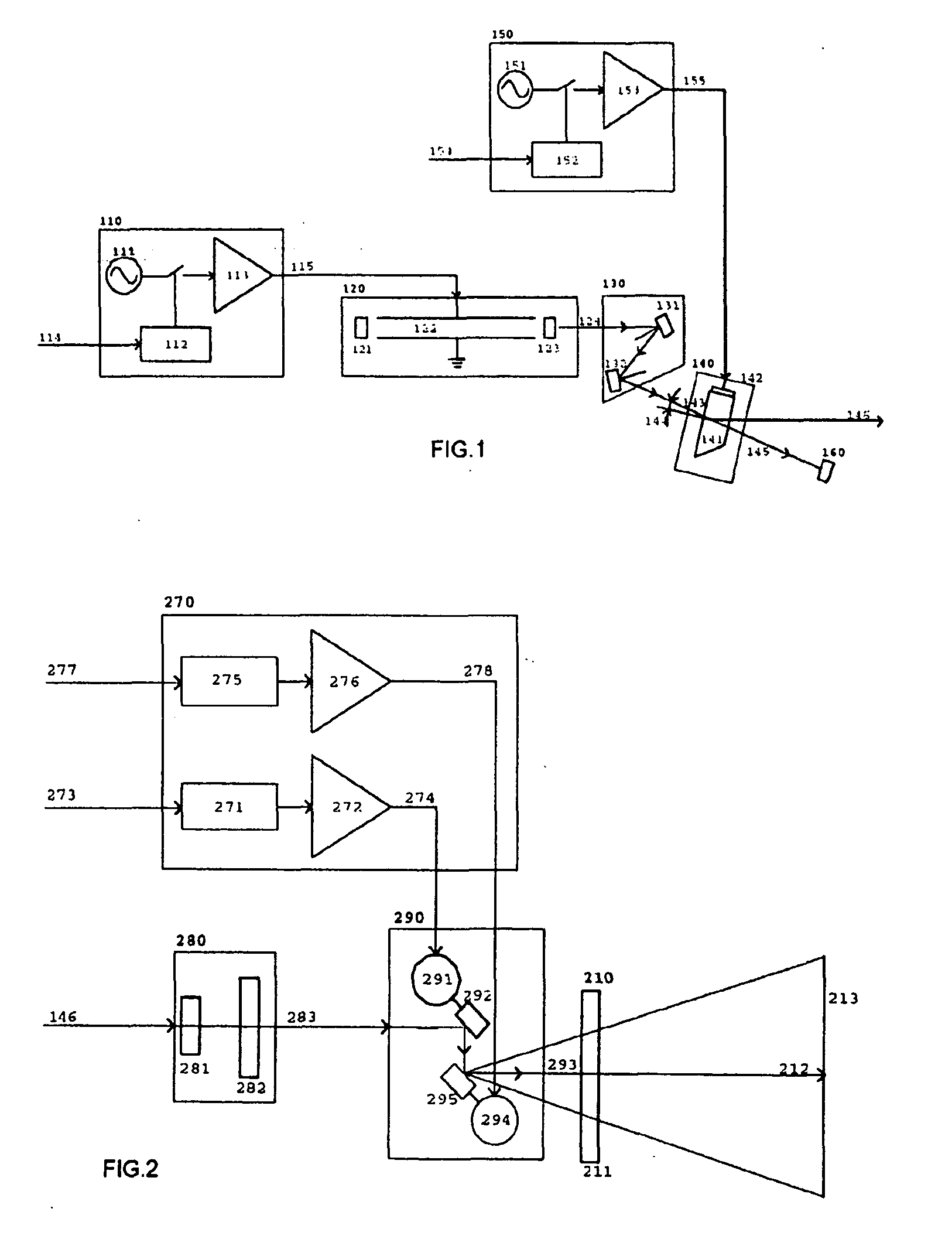
[0106]In a preferred embodiment of the invention, the configuration of the laser marking system consists of: 1) means for the generation of laser radiation based on a 100 w sealed CO2 laser, excited by radio frequency with linear polarization; 2) switching and temporaly modulating means, of at least one output port, based on a Germanium acoustic-optical modulator excited with a minimum of an RF signal which includes a minimum of 1 frequency; 3) means of collimation for each previously obtained switched beam based on a beam expander; 4) means of spatial modulation for each of the previously generated beams, based on a set of XY galvanometric scanners that have been upgraded so are able to swing up to 800 Hz to the necessary amplitude required for the application, with mirrors attached at the end of each of its shafts, able to reflect the wavelength and proper laser power concentration of the beam; and 5) means of focusing based on a f-Theta lens made of ZnSe and focal length 100 mm.

[...


PUM

PropertyMeasurementUnit
frequencyaaaaaaaaaa
frequencyaaaaaaaaaa
wavelengthaaaaaaaaaa

Abstract

The invention provides a method and device for rotary marking or machining of cylindrical materials, preferably natural cork stoppers, agglomerated cork or synthetic materials used to close wine bottles and the like. The device includes at least one feeder system of cylindrical elements, preferably natural and synthetic cork stoppers; means of sensing the presence of such cylindrical elements, a laser system, means to produce the rotation of the cylindrical elements on its axis of revolution, at a variable speed, in a tangential movement compared to the focal plane of the laser system, means of measuring the instantaneous velocity tangential to its surface and direction of rotation, optical correction and focusing means, microprocessor control based means, and means for extracting the cylindrical elements. The laser system comprises means of generating at least one laser beam; means of temporal modulation and switching for the laser beam, and means of spatial modulation of each of the laser beams in a synchronized manner with the instant tangential speed on the surface of the cylindrical element.

Description

[0001]The present invention relates to a method and a rotative marking or machining device that uses a laser radiation of cylindrical elements that allows the processing of these cylindrical elements rotating at a variable speed.BACKGROUND OF THE INVENTION[0002]At present, the marking systems For cork stoppers used in the natural cork stoppers processing industry are based on offset ink printing systems, or marking systems with hot metal marking plates warmed with electrical heaters or by induction.[0003]Also, in the case of natural cork stoppers substitutes, using synthetic materials such as polypropylene, thermoplastic foam or silicone, the process of marking is done by offset printing, tampography, thermal transfer, using special inks and drying methods to help fixing the ink to these materials, with great difficulty due to non-absorption of the material.[0004]In the state of the art, it is known and widely extended in the cork stoppers processing industry the utilization of mark...

Claims


Application Information

Patent Timeline
Patent Type & Authority Applications(United States)
IPC IPC(8): B41J2/47
CPCB41J3/4073B23K26/4035B23K2103/32B23K2103/50B23K26/0823B23K26/402
Inventor VILA CLOSAS, OSCAR
Owner ON LASER SYST & APPL
Learn More