Eureka AIR delivers breakthrough ideas for toughest innovation challenges, trusted by R&D personnel around the world.

Systems, methods, and apparatus for cryogenic refrigeration

a technology of cryogenic refrigeration and equipment, applied in the field of cryogenic cycle refrigeration systems, can solve the problems of large pumps and compressors, periodic maintenance, and the strongest and most solid materials to melt away or dispers

Active Publication Date: 2010-11-11
D WAVE SYSTEMS INC
View PDF15 Cites 39 Cited by
  • Summary
  • Abstract
  • Description
  • Claims
  • Application Information

AI Technical Summary

Benefits of technology

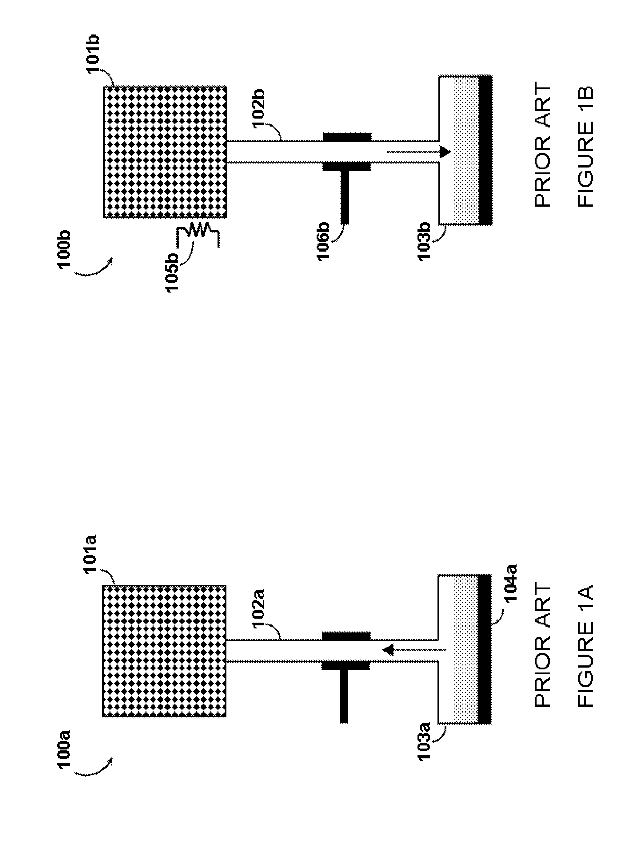
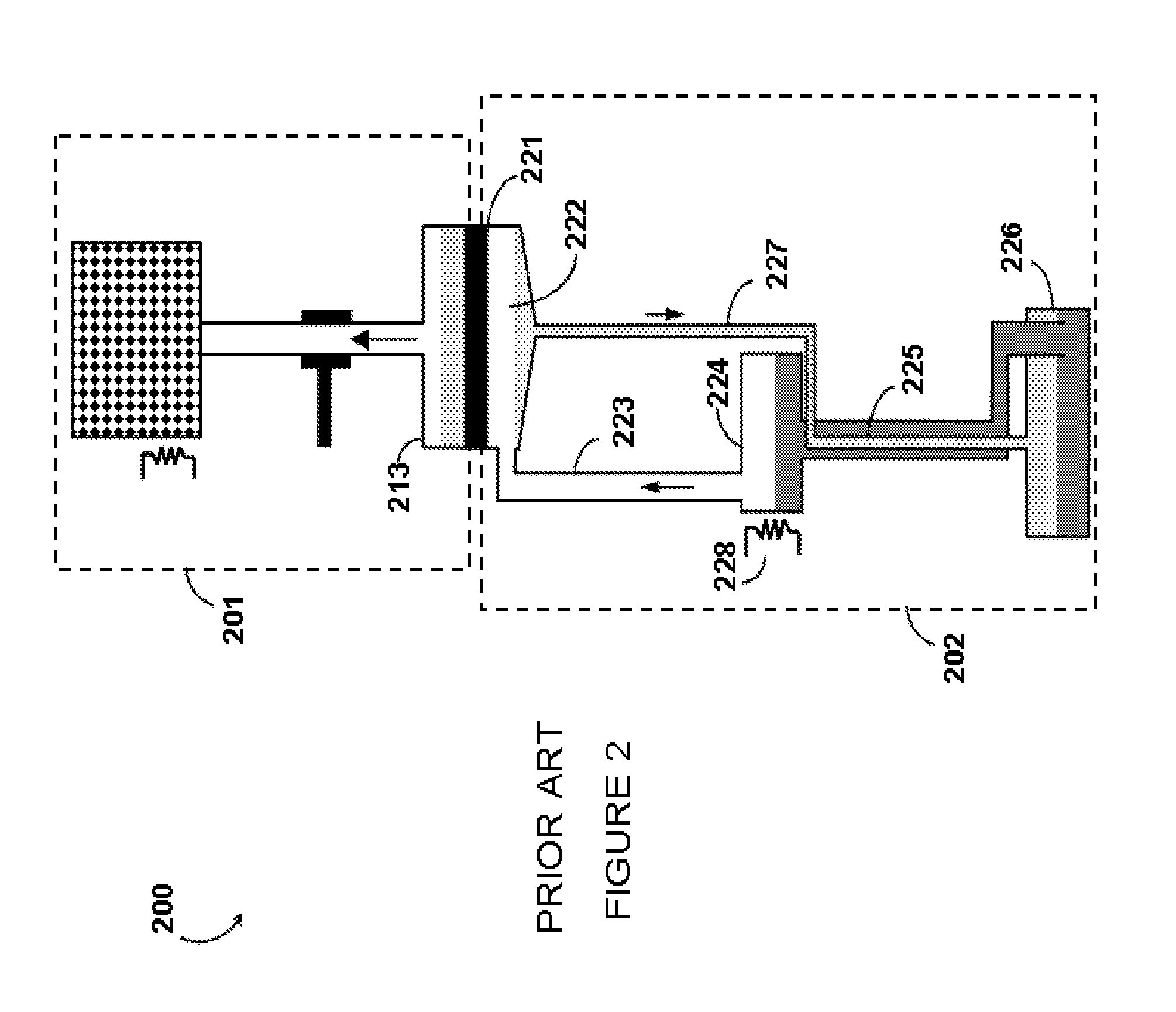
[0031]At least one embodiment may be summarized as a pulse tube cryogenic cycle refrigeration system including a pulse tube cryo-cooler having a cold head, the cold head including at least one thermal-linking point that provides cooling power at cryogenic temperature; a first adsorption pump and a second adsorption pump, wherein the first and the second adsorption pumps are both selectively thermally coupled to a thermal-linking point of the cold head; a first heating device and a second heating device, each of the first and the second heating devices positioned in close proximity to a respective one of the first and the second adsorption pumps; a first tubular channel and a second tubular channel each capable of providing fluid passage therethrough, wherein the first and the second tubular channels both include a respective condensation reg

Problems solved by technology

For instance, environments of extreme heat can cause even the strongest and most solid materials to melt away or disperse as gas.
The pumps and compressors used are large, expensive, noisy, in need of periodic maintenance, and they inevitably add contaminants to the helium that can plug fine capillaries in the dilution refrigerator, causing problems with reliability.
Filters and cold traps can be used to reduce the frequency of plugging, but these systems remain susceptible to contamination due to the smallest leaks.
The procedure of warming and subsequently cooling back down to operating temperatures can take several days.
CDRs are large, complex, composed of many pieces that are connected by numerous hoses and wires, and they require an elaborate external gas handling system for the circulation of 3He.
While these PTDR systems eliminate the need to consume helium by way of open loop evaporation, they are still expensive, large, complex, multi-piece, multi-connection systems that require an external gas handling system to bring the helium above cryogenic temperatures in providing the required circulation needed for cooling.
Due to this complexity, they are prone to leaking and plugging, and require routine and unexpected maintenance of many of the components.

Method used


Image

  • Systems, methods, and apparatus for cryogenic refrigeration
  • Systems, methods, and apparatus for cryogenic refrigeration
  • Systems, methods, and apparatus for cryogenic refrigeration

Examples


Embodiment Construction

[0061]In the following description, some specific details are included to provide a thorough understanding of various disclosed embodiments. One skilled in the relevant art, however, will recognize that embodiments may be practiced without one or more of these specific details, or with other methods, components, materials, etc. In other instances, specific detail of certain structures associated with refrigeration systems, such as thermalization links, support structures, and tubes / hoses, have not been shown or elaborated to avoid unnecessarily obscuring descriptions of the embodiments of the present systems, methods and apparatus.

[0062]Unless the context requires otherwise, throughout the specification and claims which follow, the word “comprise” and variations thereof, such as, “comprises” and “comprising” are to be construed in an open, inclusive sense, that is, as “including, but not limited to.”

[0063]Reference throughout this specification to “one embodiment,”“an embodiment” or...


PUM


Abstract

Cryogenic refrigeration employs a pulse tube cryo-cooler and a dilution refrigerator to provide very low temperature cooling, for example, to cool superconducting processors. Continuous cryogenic cycle refrigeration may be achieved using multiple adsorption pumps. Various improvements may include multiple distinct thermal-linking points, evaporation pots with cooling structures, and / or one or more gas-gap heat switches which may be integral to an adsorption pump. A reservoir volume may provide pressure relief when the system is warmed above cryogenic temperature, reducing the mass of the system. Additional heat exchangers and / or separate paths for condensation and evaporation may be provided. Multi-channel connectors may be used, and / or connectors formed of a regenerative material with a high specific heat capacity at cryogenic temperature. Flexible PCBs may provide thermal links to components that embody temperature gradients. Various components may be pre-cooled, for example via a switchable thermalization system.

Description

CROSS REFERENCE TO RELATED APPLICATIONS[0001]This application claims benefit under 35 U.S.C. 119(e) of U.S. Provisional Patent Application Ser. No. 61 / 017,460, filed Dec. 28, 2007 and entitled “Systems, Methods, and Apparatus for Cryogenic Cycle Refrigeration”; U.S. Provisional Patent Application Ser. No. 61 / 083,439, filed Jul. 24, 2008 and entitled “Systems, Methods and Apparatus for Cryogenic Refrigeration”; and U.S. Provisional Patent Application Ser. No. 61 / 086,432, filed Aug. 5, 2008 and entitled “Systems, Methods and Apparatus for Cryogenic Refrigeration”, all of which are incorporated herein by reference in their entirety.BACKGROUNDField[0002]The present systems, methods and apparatus generally relate to cryogenic cycle refrigeration systems and in particular to the use of such refrigeration systems in the field of superconducting quantum computing.Refrigeration[0003]Temperature is a property that can have a great impact on the state and evolution of a physical system. For in...

Claims


Application Information

Patent Timeline
IPC IPC(8): F17C11/00F25B19/00F25B9/00F25B41/00
CPCF25B9/10F25B9/12H01L39/02G06F2200/201H05K7/20372G06F1/20H10N60/80
Inventor BLACK, RANDALL C.HILTON, JEREMY P.ROSE, GEORDIEPETROFF, JACOB CRAIGUCHAYKIN, SERGEY V.
Owner D WAVE SYSTEMS INC
Why Eureka
Eureka Blog
Learn More