
Multi-Antenna Receiver Interference Cancellation Method and Apparatus

Inactive Publication Date: 2010-10-28
UNWIRED PLANET
View PDF4 Cites 15 Cited by
  • Summary
  • Abstract
  • Description
  • Claims
  • Application Information

AI Technical Summary

Benefits of technology

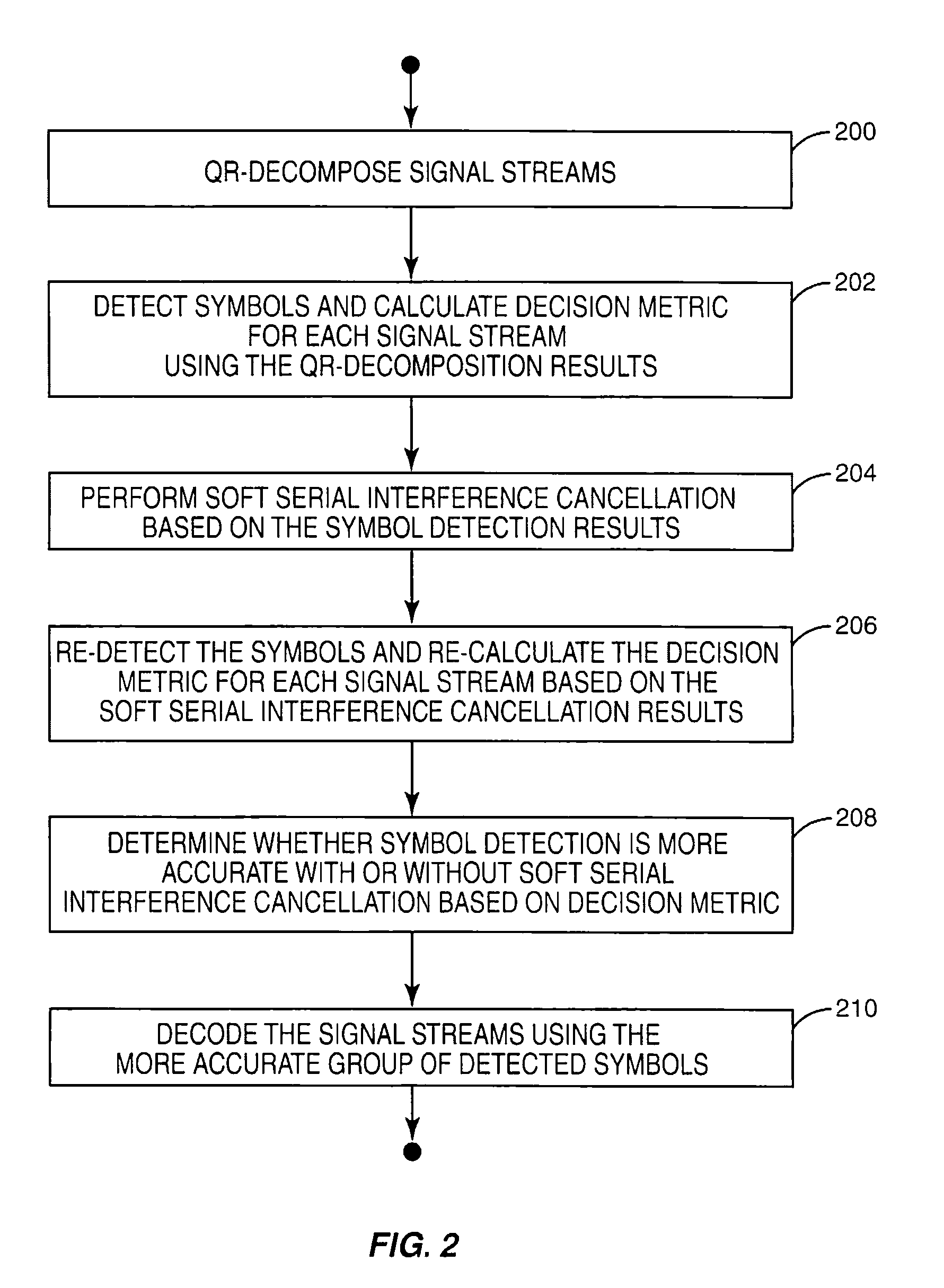
[0007]According to the methods and apparatus taught herein, a multi-antenna receiver uses QR-decomposition to detect symbols and calculate a decision metric such as Log Likelihood Ratio (LLR) for each received signal stream over one Transmission Time Interval (TTI) such as one frame or one sub-frame. The receiver then performs soft serial interference cancellation and redetects the symbols and recalculates the decision metric for each received signal stream based on the soft serial interference cancellation results. The decision metric indicates whether symbol detection is more accurate with or without soft serial interference cancellation. Comparing the decision metric calculations for at least one of the signal streams allows the receiver to determine whether soft serial interference cancellation improves symbol detection accuracy. If so, the symbols detected based on the interference cancellation results are decoded and coherently combined to detect the transmitted signal. Otherwise, the symbols detected before interference cancellation was performed are decoded. This way, the more accurate group of detected symbols is used to decode the transmitted signal. For example, if soft serial interference cancellation yields too many symbol detection errors as indicated by the decision metric, the resulting symbols are not decoded. Instead, the symbols detected based on the QR-decomposition results are decoded.
[0008]Moreover, the multi-antenna receiver can attempt at least once to re-decode unsuccessfully decoded signal streams. That is, if one or more signal streams are not properly decoded, the corresponding decoding results pend while the receiver attempts to decode the remaining signal streams. Accordingly, the receiver does not stop decoding because one signal stream was improperly decoded. Instead, the receiver attempts at least once to re-decode any unsuccessfully decoded signal streams. Decoding accuracy is further improved because interference from successfully decoded signal streams is cancelled from the composite signal before re-decoding is attempted. This way, when the receiver attempts to re-decode unsuccessfully decoded signal streams, it does so absent interference from successfully decoded streams. The receiver may optionally re-rank the unsuccessfully decoded signal streams based on the decision metric calculations before attempting to re-decode the symbols. This further improves re-decoding accuracy because the signal streams most likely to be re-decoded successfully are processed first and their contribution removed before the receiver attempts to re-decode the remaining signal streams. Attempting more than once to re-decode signal streams reduces the number of Negative Acknowledgement (NACK) requests issued by the receiver, improving data throughput.
[0010]Summarizing the potential effect each component provides, multi-stage iterative soft serial cancellation yields receive antenna diversity gain, soft interference cancellation reduces error propagation due to symbol detection error or decoding error, QR decomposition reduces symbol detection error, and selection between detected symbols with and without cancellation based on a metric reduces decoding error. Of course, the present invention is not limited to the above features and advantages. Those skilled in the art will recognize additional features and advantages upon reading the following detailed description, and upon viewing the accompanying drawings.

Problems solved by technology

Accordingly, the receiver does not stop decoding because one signal stream was improperly decoded.

Method used


Image

  • Multi-Antenna Receiver Interference Cancellation Method and Apparatus
  • Multi-Antenna Receiver Interference Cancellation Method and Apparatus
  • Multi-Antenna Receiver Interference Cancellation Method and Apparatus

Examples


Embodiment Construction

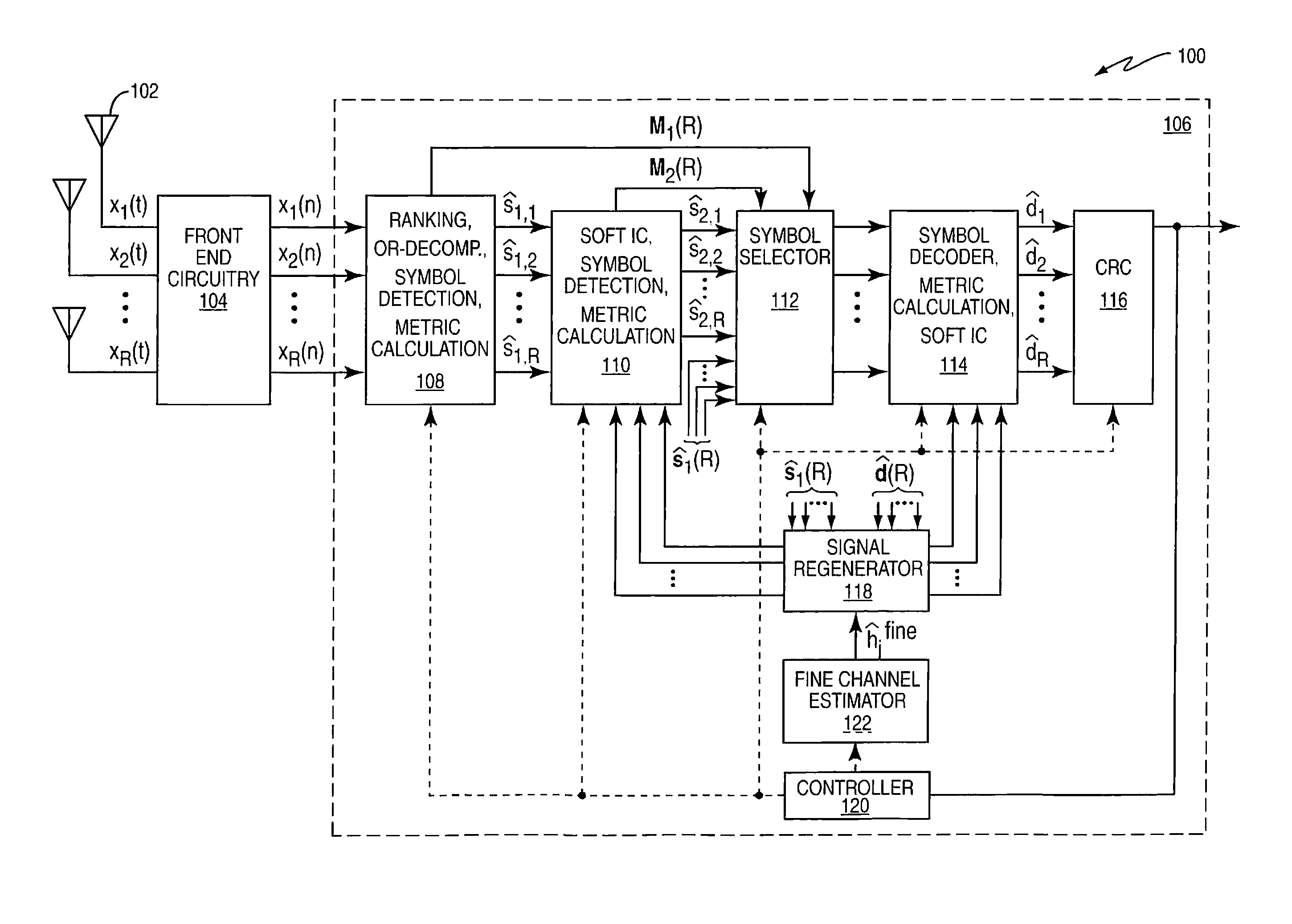
[0018]FIG. 1 illustrates an embodiment of a receiver 100 having R antennas 102 for receiving a signal transmitted over different signal propagation paths. The signals as a function of time (t) x1(t), x2(t), . . . , xR(t) received at the different antennas 102 each have contributions from different ones of the transmit antennas (not shown). The received signals are filtered, down-converted and digitized by front end circuitry 104 to form corresponding baseband signal streams as a function of symbol index (n) x1(n), x2(n), . . . , xR(n). The composite baseband signal vector x=[x1(n), x2(n), . . . xR(n)]T is processed by a baseband processor 106 included in the receiver 100 to decode the transmitted signal.

[0019]In one embodiment, the baseband processor 106 detects symbols for each signal stream before and after performing interference cancellation on the composite baseband signal. A decision metric is also calculated for each signal stream before and after interference cancellation. T...


PUM


Abstract

A composite signal including a plurality of component signal streams is processed using QR-decomposition to detect symbols and calculate a decision metric for each of the signal streams (202). Soft serial interference cancellation is performed on the composite signal based on the symbols detected for different ones of the signal streams and a ranking of the signal streams (204). The symbols are re-detected and the decision metric re-calculated for each signal stream based on soft serial interference cancellation results (206). The different decision metric calculations for at least one of the signal streams are compared to determine whether symbol detection is more accurate with or without soft serial interference cancellation (208). The signal streams are decoded using symbols detected based on soft serial interference cancellation results when symbol detection is determined to be more accurate with soft serial interference cancellation (210). Otherwise, the streams are decoded based on the symbols detected using QR-decomposition (210).

Description

TECHNICAL FIELD OF THE INVENTION[0001]The present invention generally relates to multiple-input multiple-output (MIMO) based communication networks, and particularly relates to cancelling signal interference in MIMO based networks.BACKGROUND[0002]MIMO (Multiple Input and Multiple Output) is an essential technology to increase peak data rate or throughput for wireless communications. In a MIMO-based system, the transmitter has multiple antennas for transmitting information to a receiver. Each transmit antenna radiates energy representing the signal being transmitted. The receiver also has multiple antennas for receiving the transmitted signals. The signal received at each antenna has contributions from different ones of the transmit antennas. In a case of multi-layer transmission, where different transmission antenna transmit different information and in a case where there is no feedback information about the channel to the transmitter, the receiver attempts to separate out the diffe...

Claims


Application Information

Patent Timeline
IPC IPC(8): H04B1/10
CPCH04B7/0413H04B7/0854H04L25/03006H04L1/06H04L1/1812H04L1/005
Inventor MURAI, HIDESHIGORANSSON, BO
Owner UNWIRED PLANET
Learn More