
Method and device for detecting vertical bell laboratories layered space-time codes

a technology of layered spacetime and codes, applied in the field of wireless communication, can solve the problems of limited method performance, limited method error ratio, and limited wireless communication, and achieve the effect of improving the detection performance of v-blast and reducing error propagation

Active Publication Date: 2005-10-27
ALCATEL LUCENT SAS
View PDF8 Cites 15 Cited by
  • Summary
  • Abstract
  • Description
  • Claims
  • Application Information

AI Technical Summary

Benefits of technology

[0031] With regard to the aforesaid two existing detection methods, the present invention proposes a V-BLAST detection method capable of further reducing V-BLAST inter-layer error propagation so that the error code performance can be further improved.
[0042] The V-BLAST detection method and the V-BLAST detection device according to the present invention can suppress the inter-layer error propagation of V-BLAST better and hence remarkably improve the error code performance of V-BLAST.

Problems solved by technology

However, different from wire communication, wireless communication is restricted by various factors such as spectrum resource, transmission power and multi-path fading, among which the spectrum efficiency becomes a focus of attention because it directly affects the capacity of a wireless communication system.
Therefore, this method is relatively complicated in case of comparatively many transmitting antennae.
In addition, the performance of error ratio of the method is much restricted due to error propagation between layers of V-BLAST.
However, the detecting procedure is too complicated, and still has inter-layer error propagation.
Its error performance is still restricted to a certain extent.

Method used


Image

  • Method and device for detecting vertical bell laboratories layered space-time codes
  • Method and device for detecting vertical bell laboratories layered space-time codes
  • Method and device for detecting vertical bell laboratories layered space-time codes

Examples


Embodiment Construction

[0048] The V-BLAST detection method and device according to the invention will be described in detail in conjunction with the drawings.

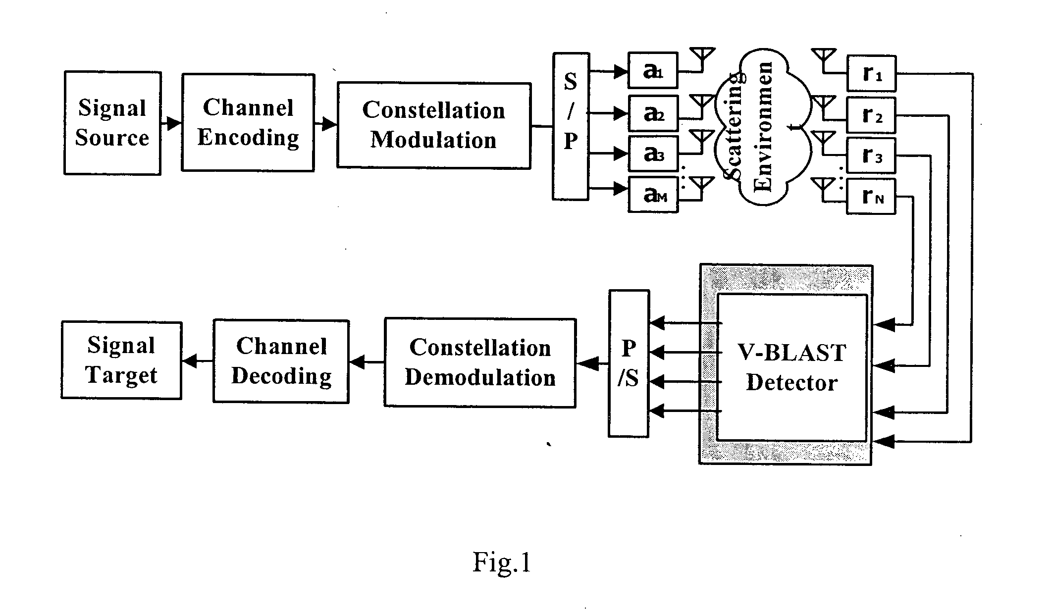
[0049]FIG. 1 shows a MIMO system in which signals are detected with the V-BLAST detection method according to the invention. As stated above, this system has M transmitting antennae and N receiving antennae, wherein 11, a2, . . . , aM)Trepresents a vector with M rows and 1 column obtained by transposing the vector (a1, a2, . . . , aM).

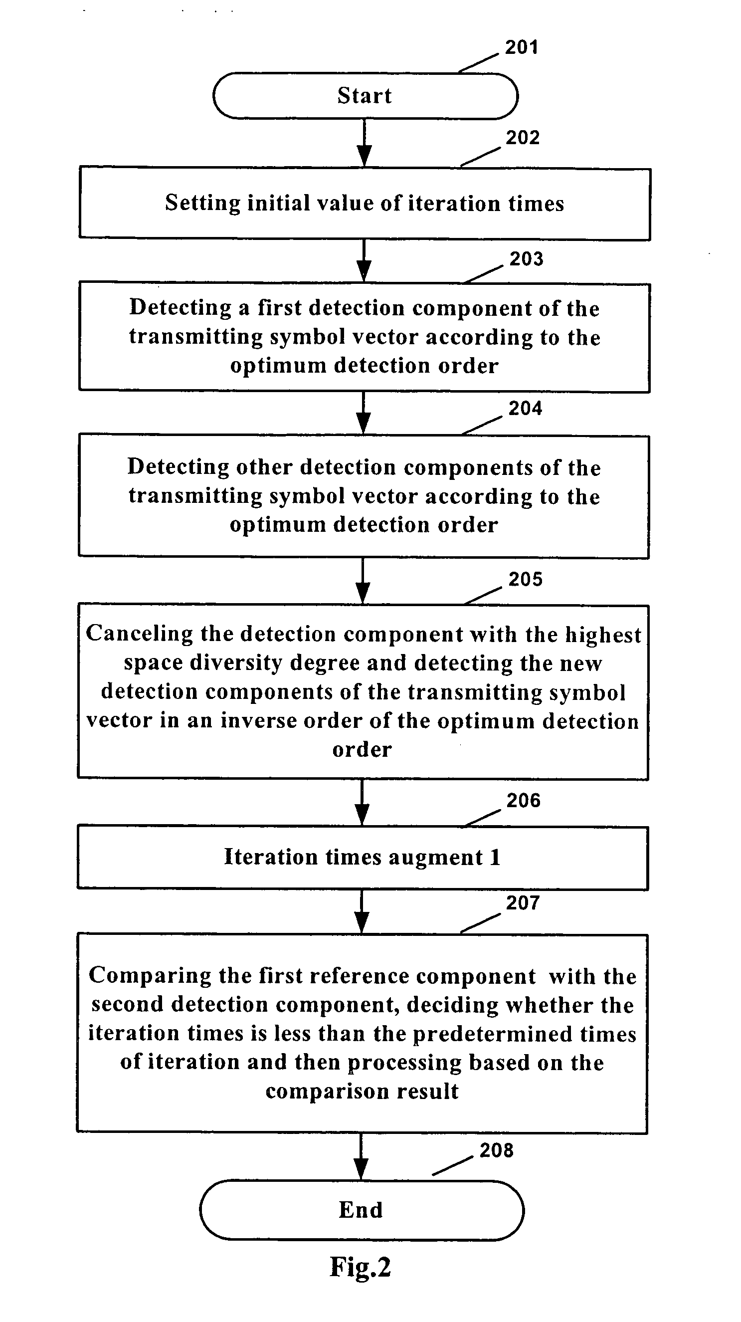
[0050] The V-BLAST detection method according to the invention is, on the basis of the aforesaid Ordering-SIC V-BLAST detection method, realized by further introducing outer close loop iteration steps. FIG. 2 shows a flow chart of the V-BLAST detection method according to the invention.

[0051] As shown in FIG. 2, the method starts at step 201. In step 202, the initial value of iteration times is set as 0.

[0052] After that, the procedure comes to step 203. In step 203, the first detection component of the transmitting...


PUM


Abstract

The present invention discloses a V-BLAST detection method for a MIMO system, including: a first detecting step for acquiring in sequence the old detection components of a transmitting symbol vector with the optimum ordering-successive interference cancellation detection method; a second detecting step for taking the detection component with the highest space diversity degree among the old detection components as a first new lo detection component, and acquiring in sequence the other new detection components of the transmitting symbol vector in an inverse order of the optimum detection order with the optimum ordering-successive interference cancellation detection method; an outputting step for outputting the first new detection component and the other new is detection components as the final detection result. The method according to the invention employs the outer close loop iteration technology to further reduce inter-layer error propagation of V-BLAST. This method has less complexity.

Description

CROSS-REFERENCE TO RELATED APPLICATIONS(S) [0001] This application is based on the Chinese Patent Application No. 200410017647.1 filed on Apr. 13, 2004, the disclosure of which is hereby incorporated by reference thereto in its entirety, and the priority of which is hereby claimed under 35 U.S.C. §119. TECHNICAL FIELD [0002] The present application relates to the field of wireless communication, in particular to a method and a device for detecting Vertical Bell Laboratories Layered Space-Time (V-BLAST) codes. BACKGROUND ART [0003] With the development of wireless communication technology and diversification of information demands, people gradually transfer their attention from pure voice services to multi-media services. However, different from wire communication, wireless communication is restricted by various factors such as spectrum resource, transmission power and multi-path fading, among which the spectrum efficiency becomes a focus of attention because it directly affects the ...

Claims


Application Information

Patent Timeline
Patent Type & Authority Applications(United States)
IPC IPC(8): H04B7/04H04B7/06H04B7/08
CPCH04B7/04H04B7/0891H04B7/0854
Inventor LI, DONGYANG, HONGWEICAI, LIYU
Owner ALCATEL LUCENT SAS
Learn More